Featured Projects
Explore and run example projects — organized by board
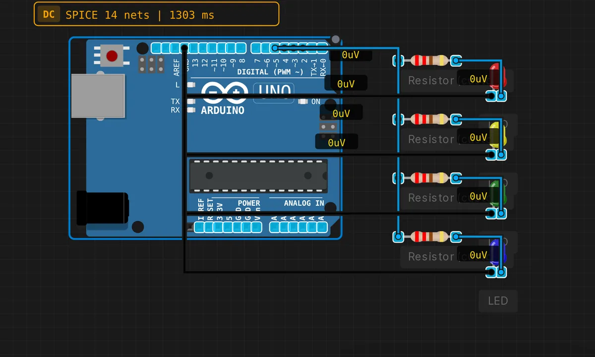
4-bit Binary Counter
Count from 0 to 15 displayed on 4 LEDs. Each LED = one bit.
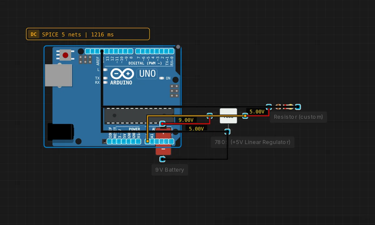
7805 Regulated Power Supply
9V battery → 7805 → stable 5V for the Arduino. Classic linear regulator.
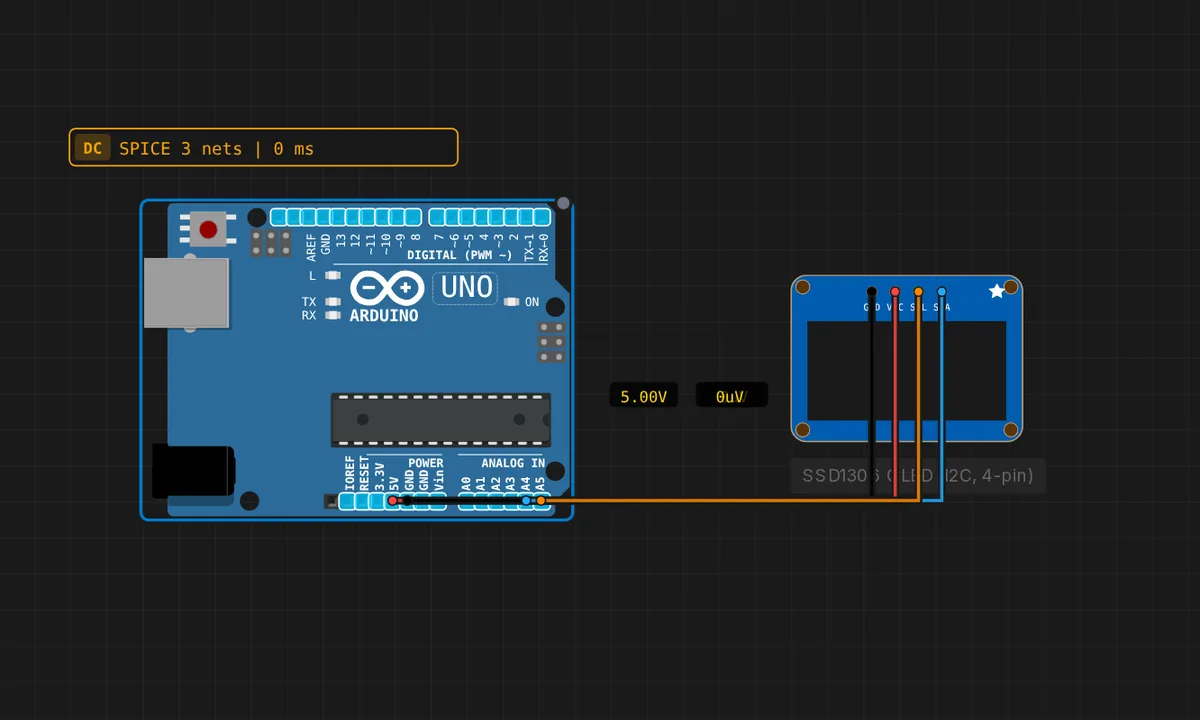
Arduino Uno: SSD1306 OLED (4-pin I2C)
Drive the cheap 4-pin SSD1306 OLED module (GND/VCC/SCL/SDA) over I2C from an Arduino Uno (SDA=A4, SCL=A5). Shows "Hello Velxio!" with a live counter.
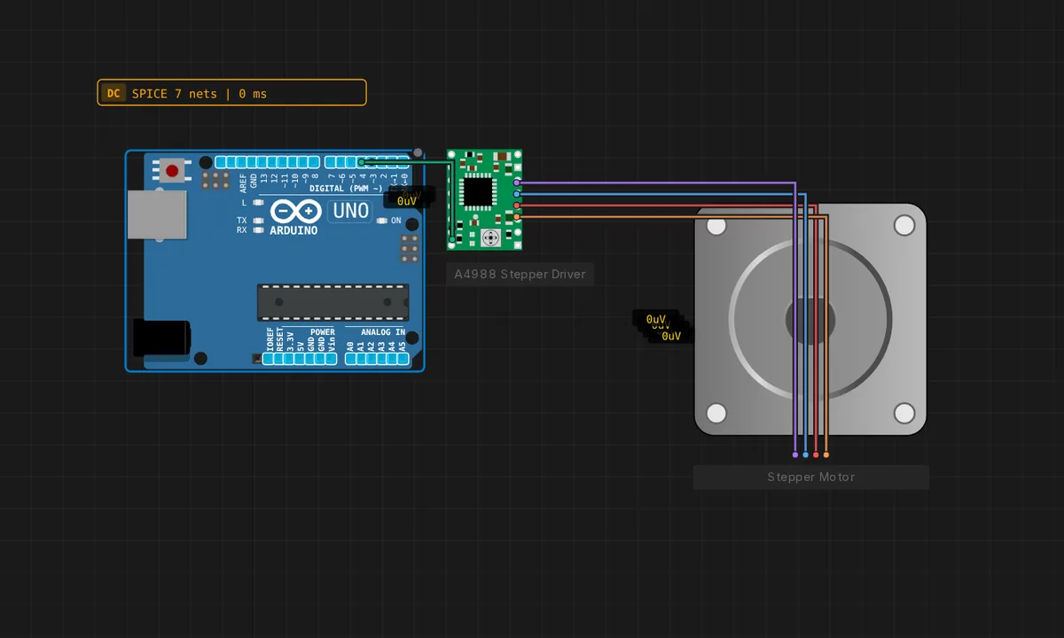
Arduino Uno: Stepper + A4988
Spin a bipolar stepper motor from an Arduino Uno through an A4988 driver. The MCU only pulses STEP and sets DIR; the A4988 drives the coils. The rotor turns continuously.
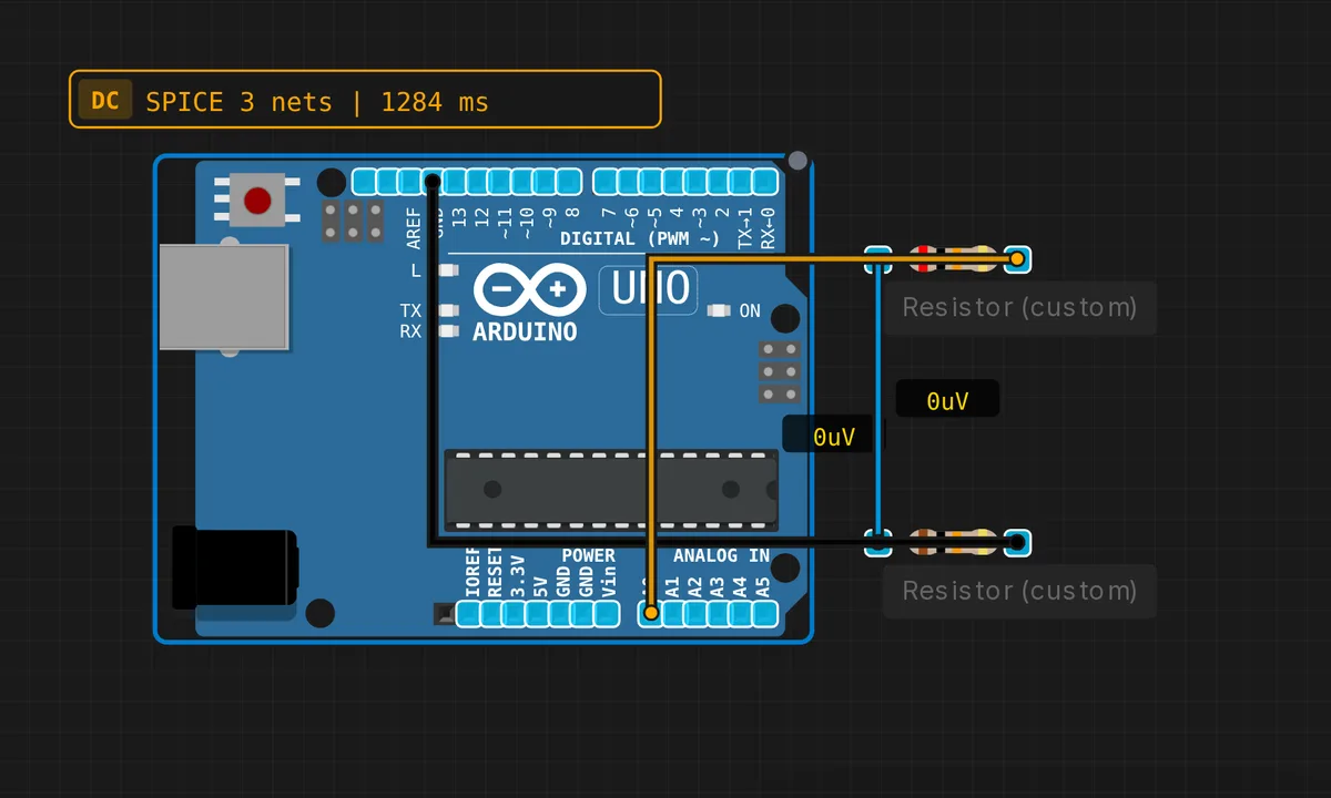
Battery Voltage Monitor
Voltage divider scales 9V battery down to 0-5V range for ADC measurement.
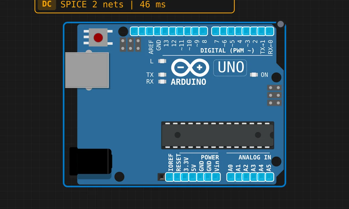
Blink LED
Classic Arduino blink example - toggle an LED on and off
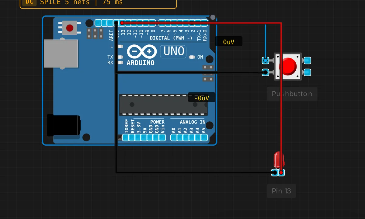
Button Control
Control an LED with a pushbutton
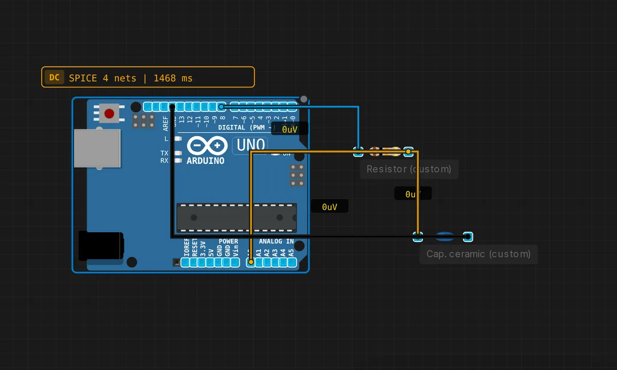
Capacitor Charging Curve
Charge a capacitor through a resistor, read the exponential V(t) via ADC.
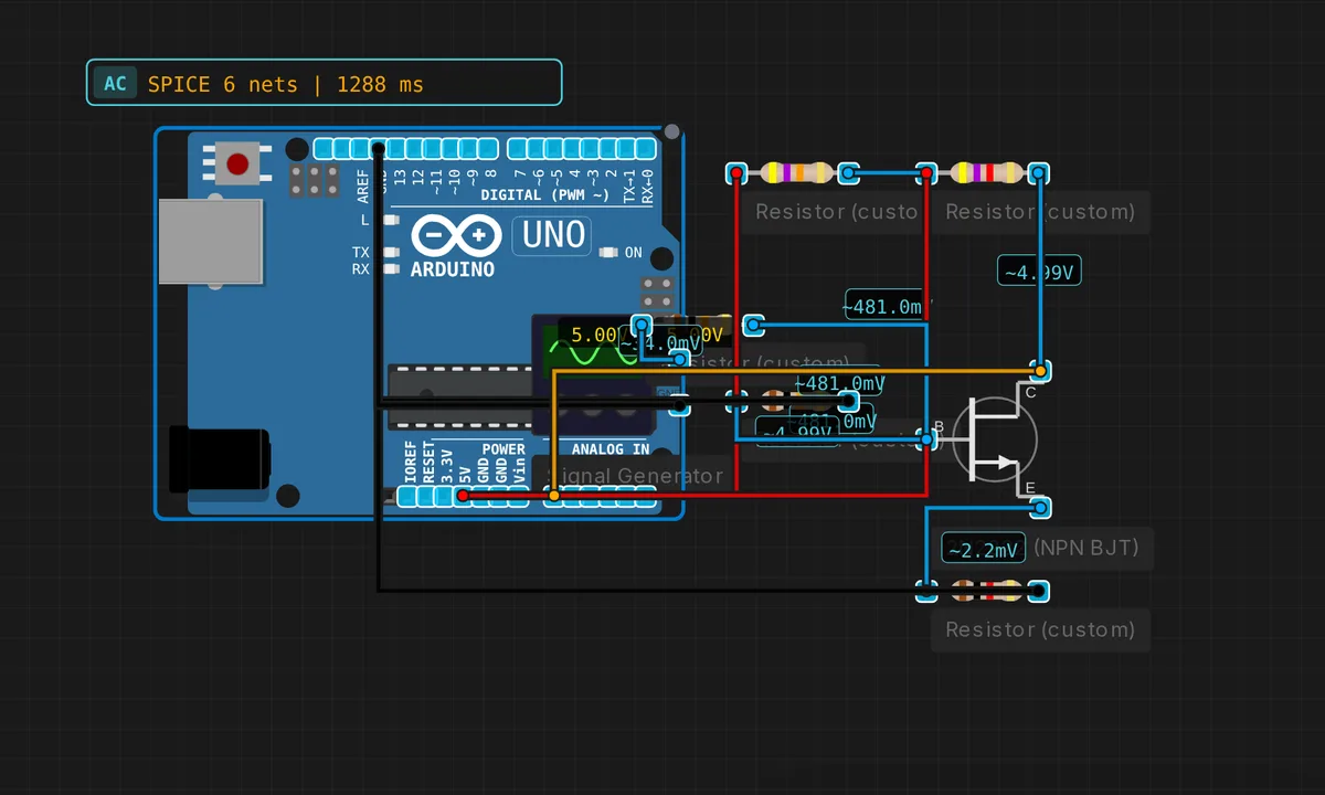
Common-Emitter Amplifier
NPN BJT amplifies a small AC signal. Gain = -Rc/Re.
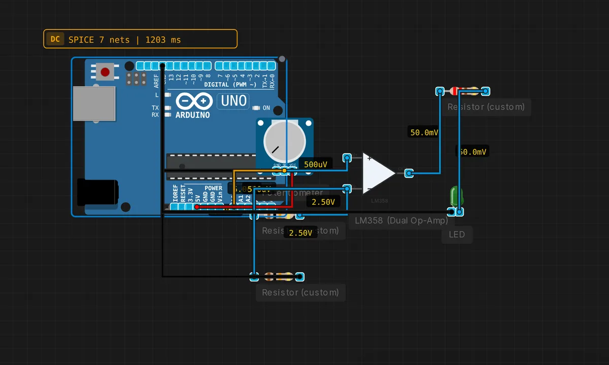
Comparator with LED
Op-amp compares pot voltage vs 2.5V reference. LED indicates which is higher.
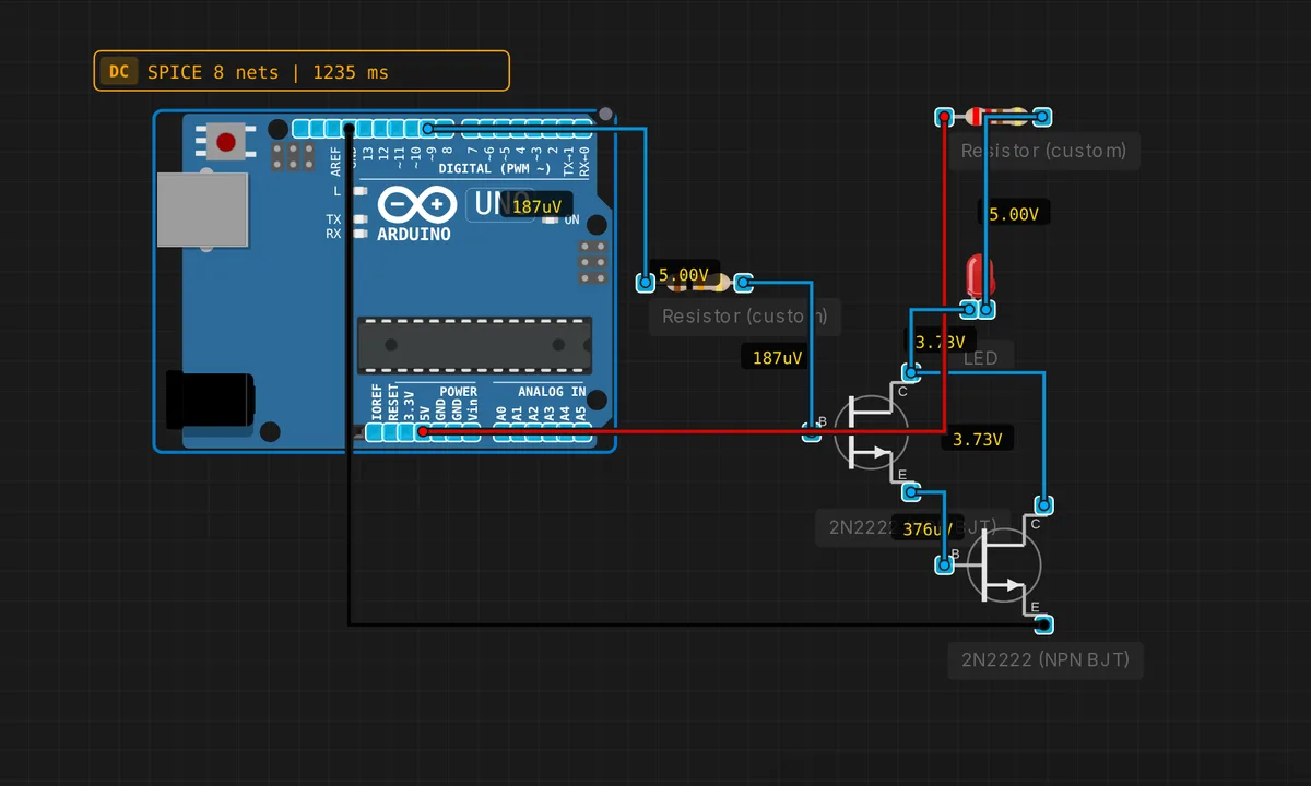
Darlington Pair (High Current)
Two NPN BJTs cascaded for beta-squared current gain. Drives heavy loads from MCU.
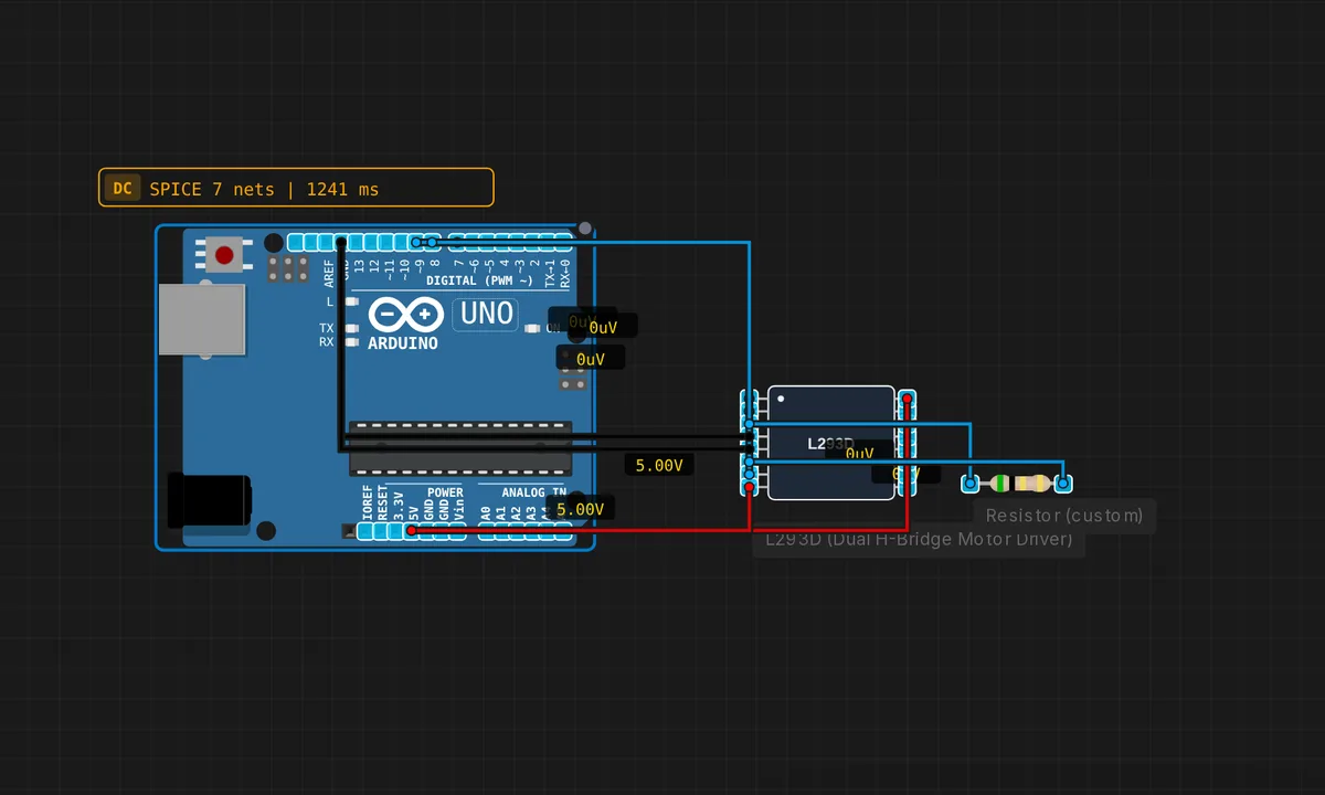
DC Motor Control (L293D)
L293D H-bridge drives a DC motor forward, reverse, and brake.
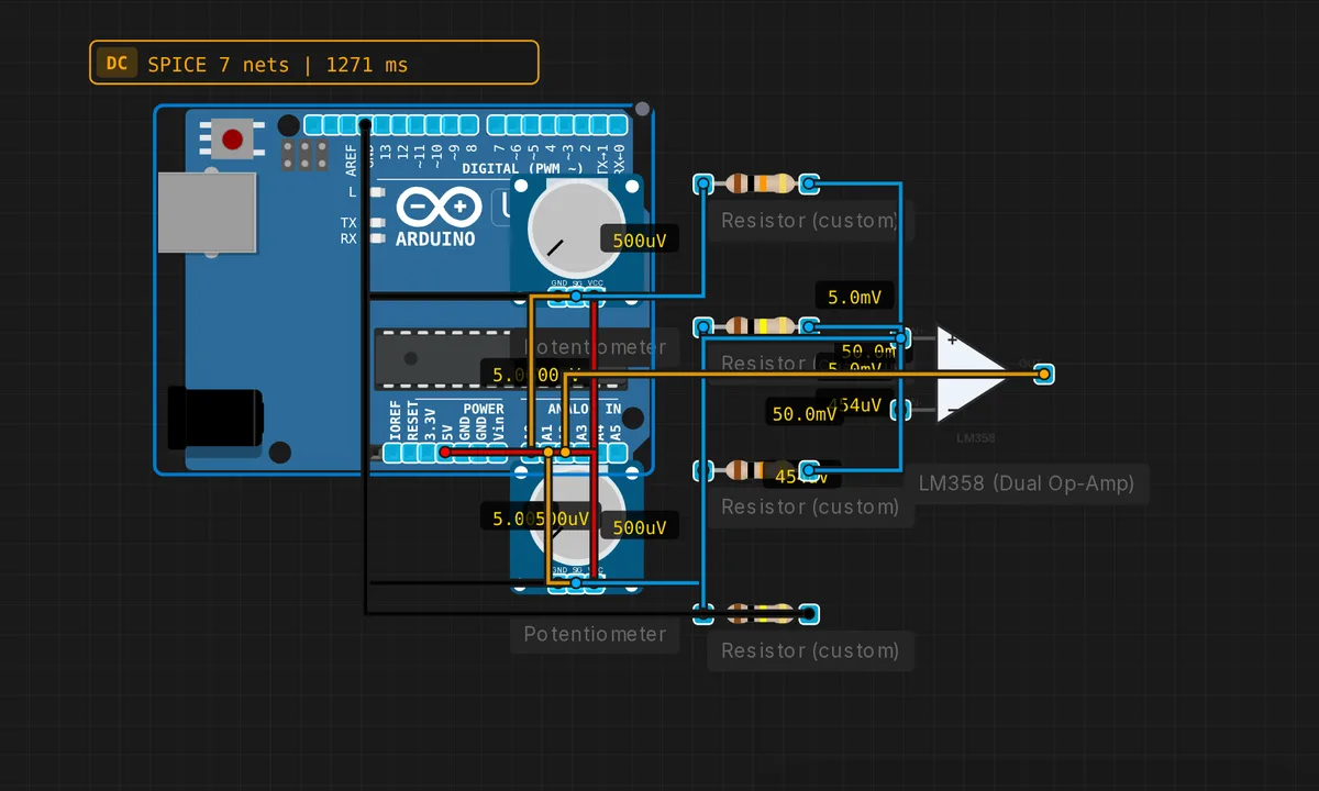
Difference Amplifier
Vout = Gain * (V2 - V1). Useful for bridge sensors and differential signals.
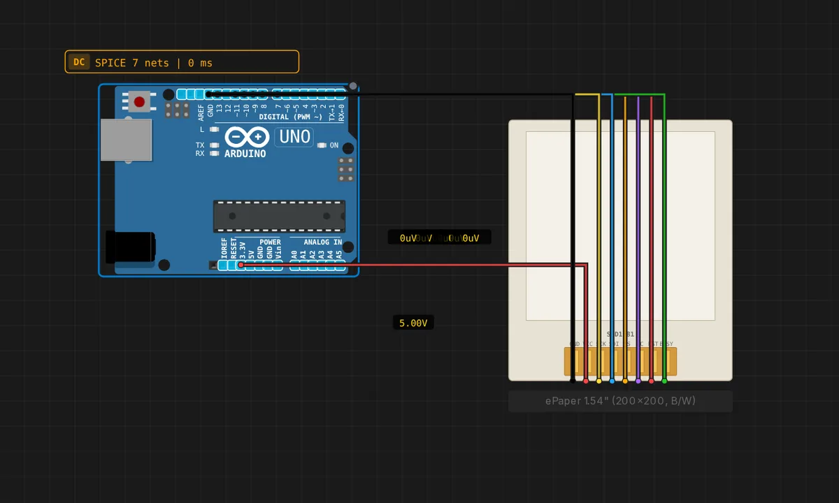
ePaper 1.54" Hello — Arduino Uno
GxEPD2 paged-mode "Hello, Velxio" on a 200×200 SSD1681 e-Ink panel driven by an Arduino Uno. The smallest panel that fits in Uno's 32 KB flash + 2 KB SRAM at 16-row page height.
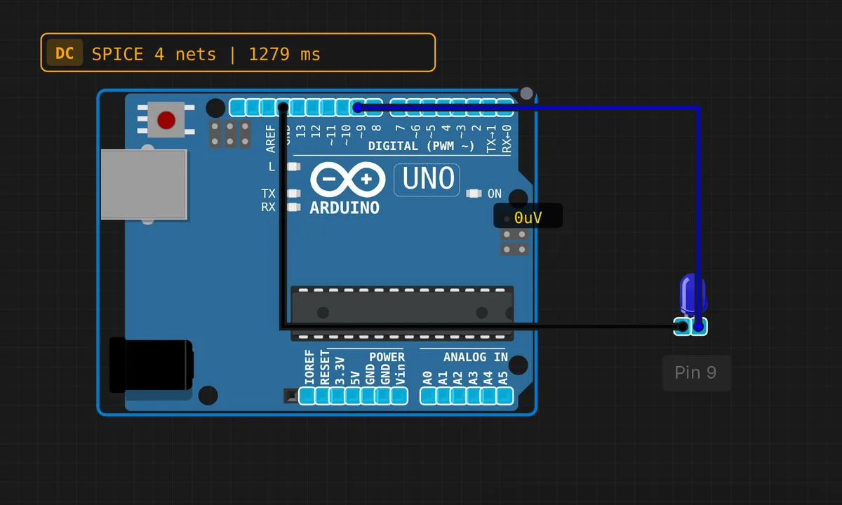
Fade LED
Smoothly fade an LED using PWM
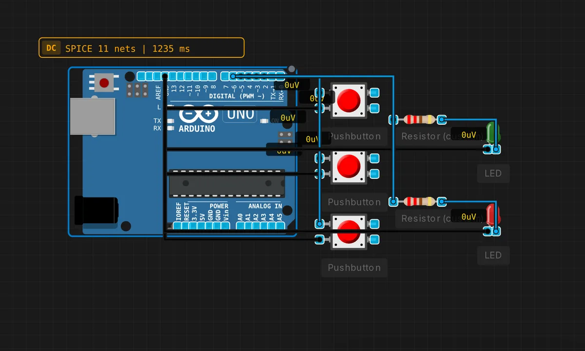
Full Adder (1-bit)
Sum = A XOR B XOR Cin, Cout = (A AND B) OR (Cin AND (A XOR B)).
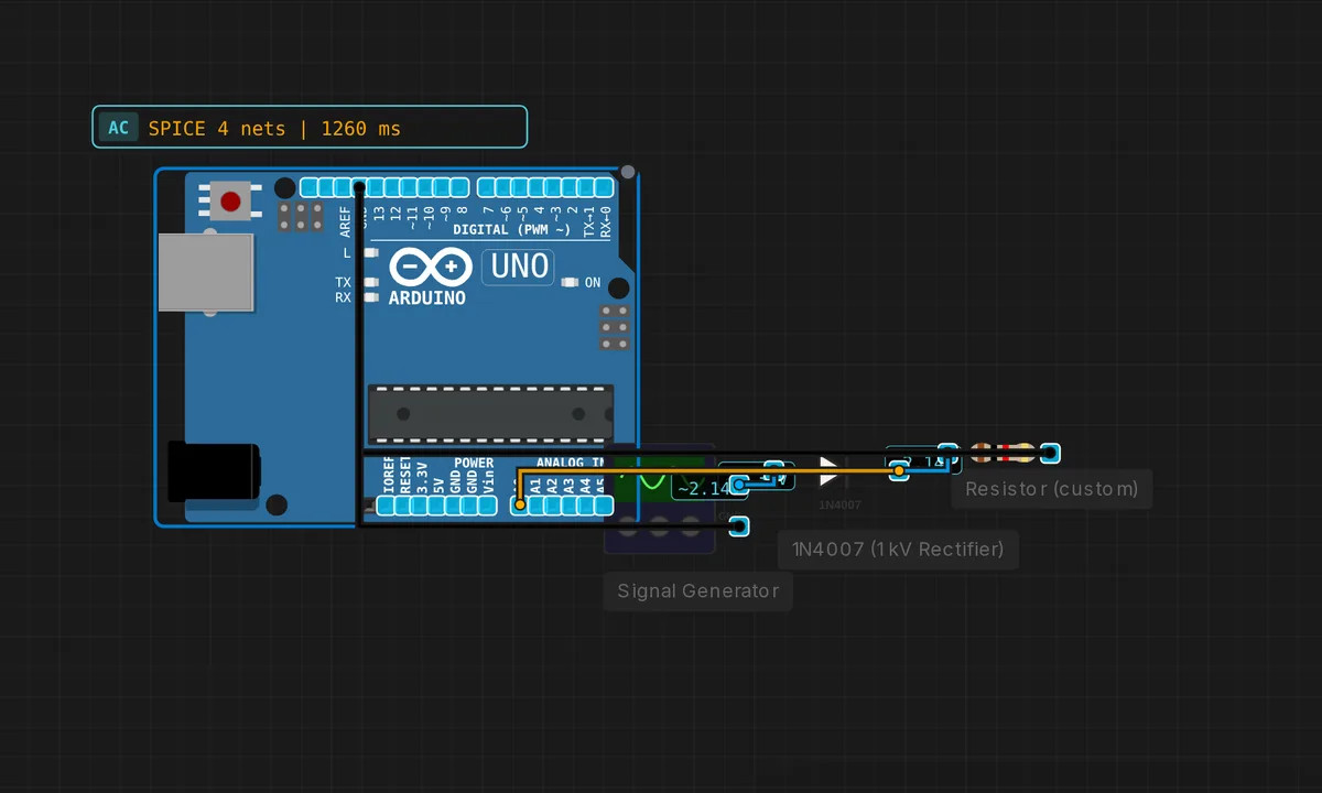
Half-Wave Rectifier
Diode passes only positive half-cycles. Read rectified output on ADC.
I2C EEPROM Read/Write
Writes data to a virtual I2C EEPROM (0x50) and reads it back. Tests TWI write+read transactions.
I2C RTC Clock (DS1307)
Reads time from a virtual DS1307 RTC via I2C and prints it to Serial. Tests TWI read transactions.
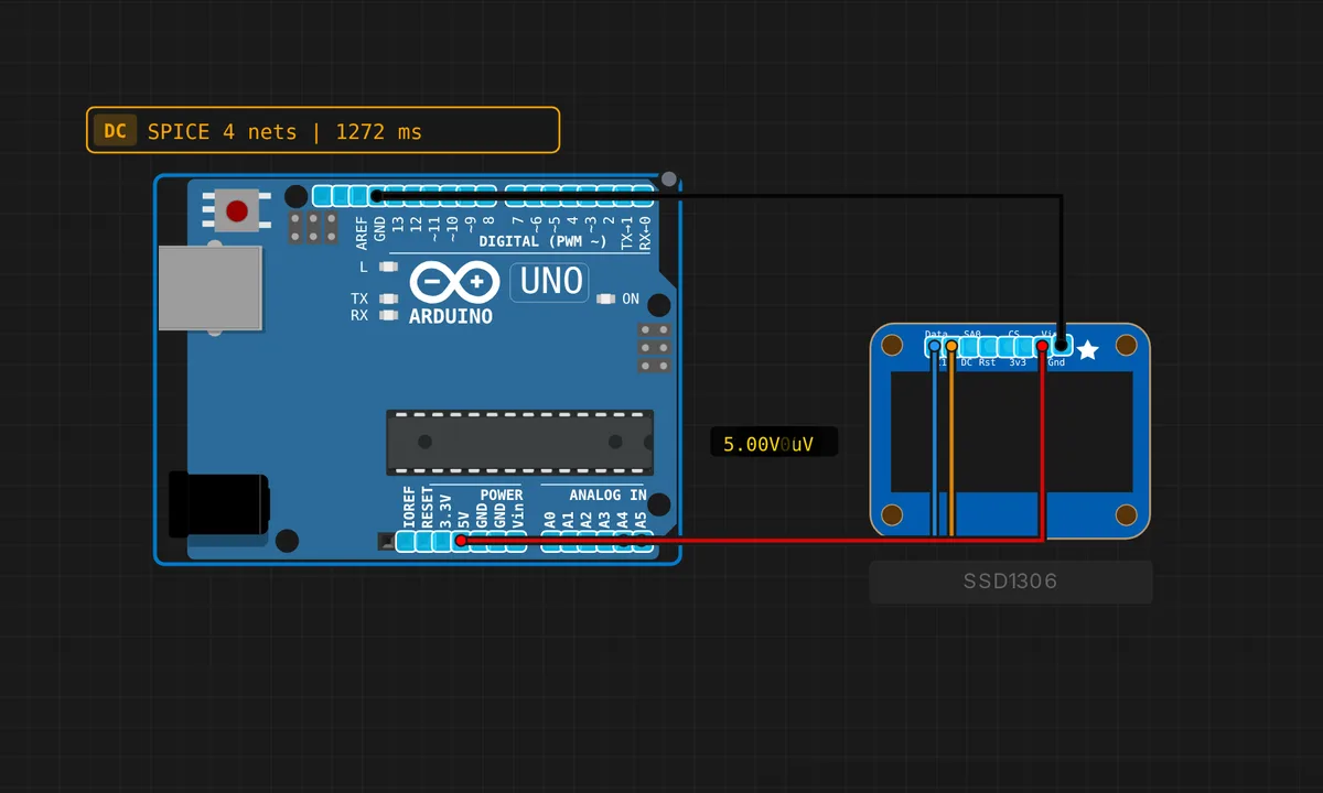
I2C Scanner (TWI)
Scans the I2C bus and reports all devices found. SSD1306 OLED (0x3C) is wired on canvas; virtual devices at 0x48, 0x50, 0x68 also respond.
Intel 8080 Banner Streamer
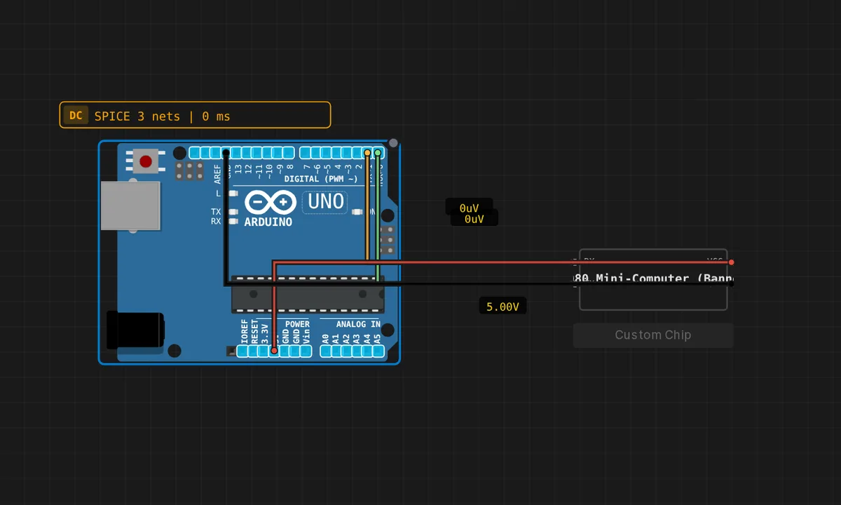
A clean-room Intel 8080 boots from a 328-byte embedded ROM, prints a banner, then prints "uptime ticks: 0xNN" every ~50 ms. Open the Serial Monitor to watch.
Inverting Amplifier (LM358)
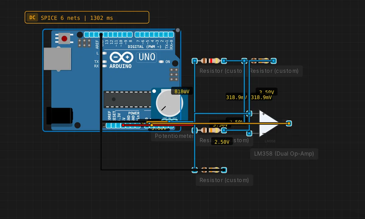
Vout = -(Rf/Rin) * Vin. Gain=-10 with Rin=1k, Rf=10k.
KY-040 Rotary Encoder
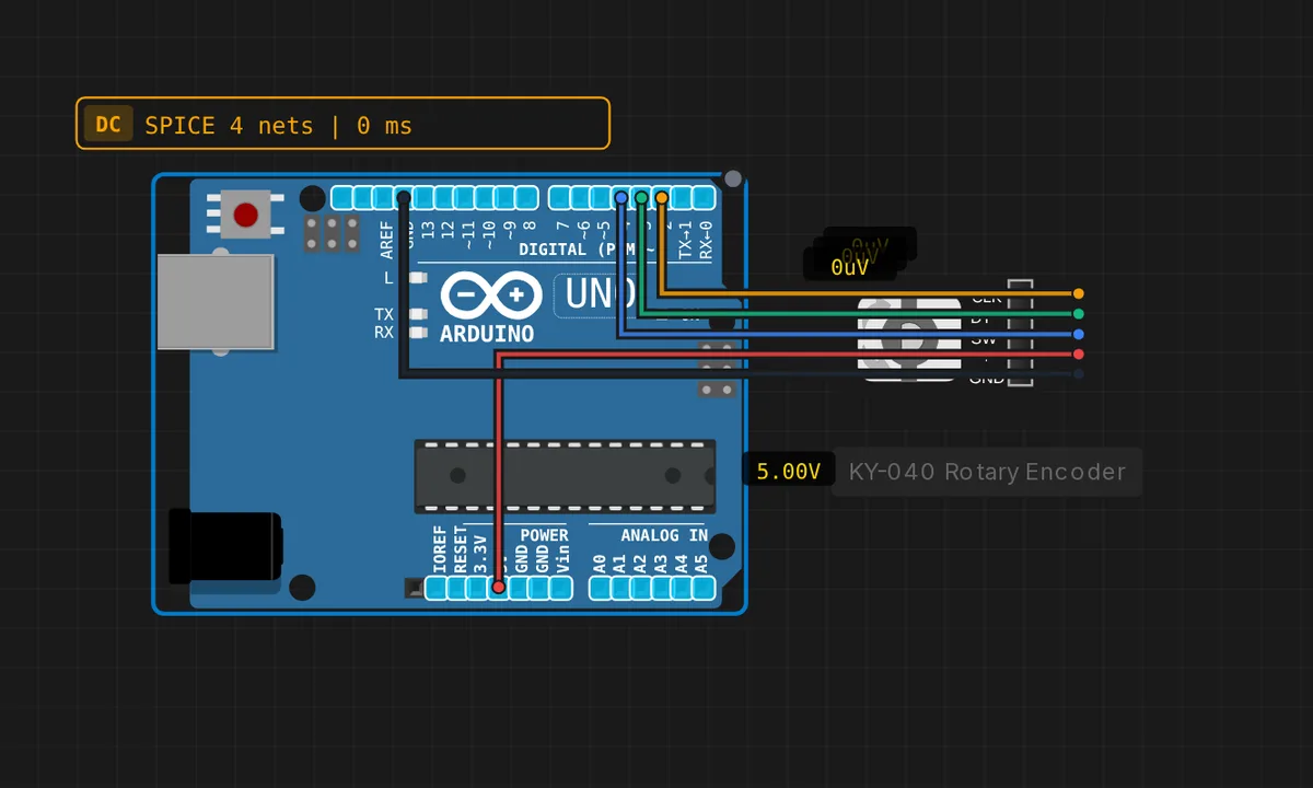
Read a KY-040 rotary encoder with an Arduino Uno. Turn the knob to move a counter (CLK/DT quadrature) and press the shaft (SW) to reset it. Open the Serial Monitor to watch the position.
LCD 20x4 Display
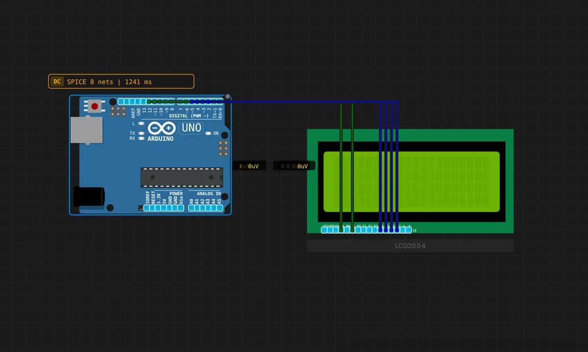
Display text on a 20x4 LCD using the LiquidCrystal library
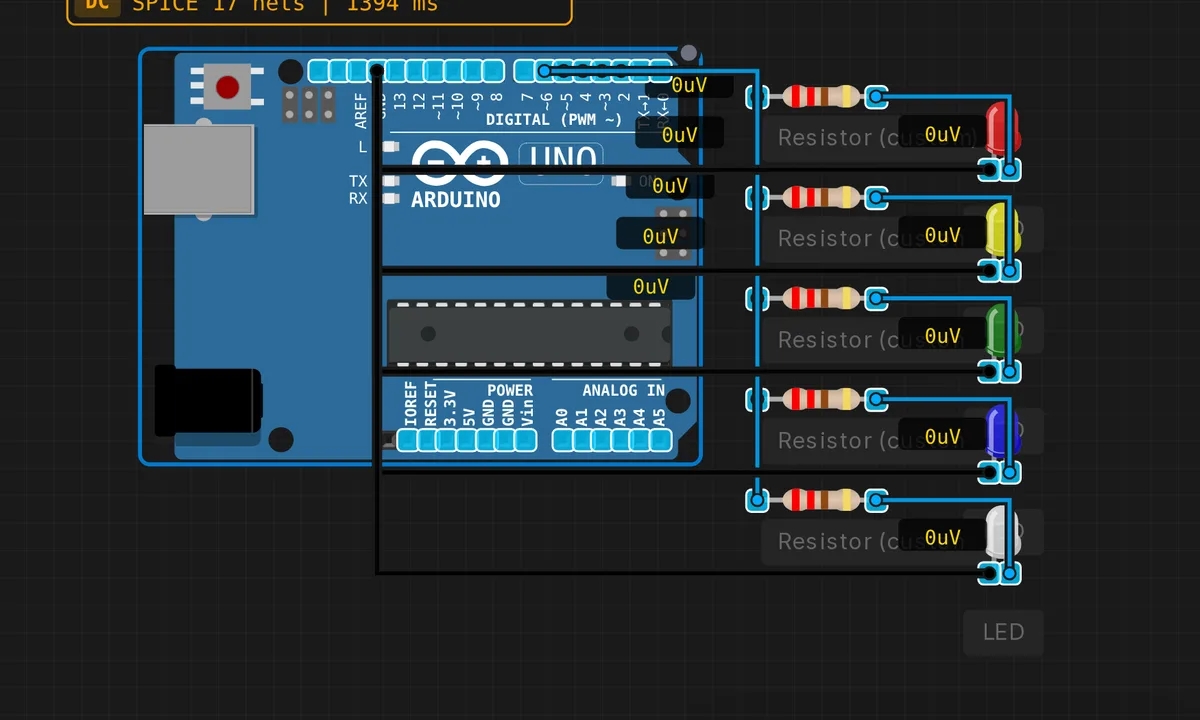
LED Bar Graph
5 LEDs driven from digital pins with individual resistors. Bargraph display.
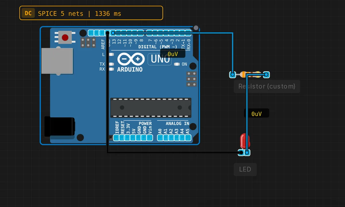
LED with Current-Limiting Resistor
Calculate R to set LED current to 10mA. I = (Vcc-Vf)/R.
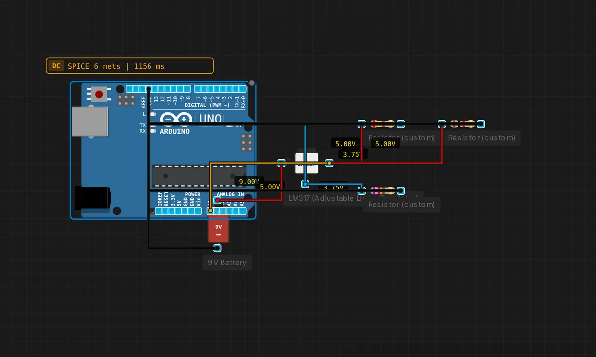
LM317 Adjustable PSU
LM317 with R1/R2 divider. Vout = 1.25 * (1 + R2/R1). Set any voltage 1.25-37V.
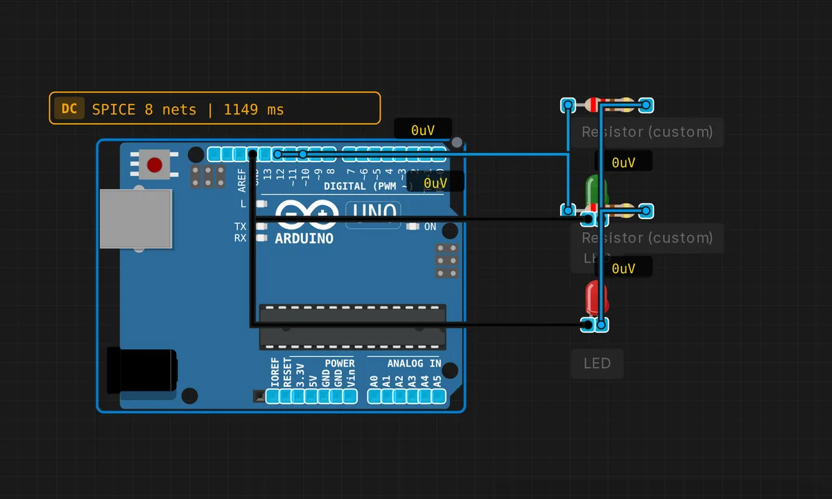
Logic Probe (HIGH/LOW/FLOATING)
Read any digital pin state and show on 3 LEDs: green=HIGH, red=LOW, yellow=floating.
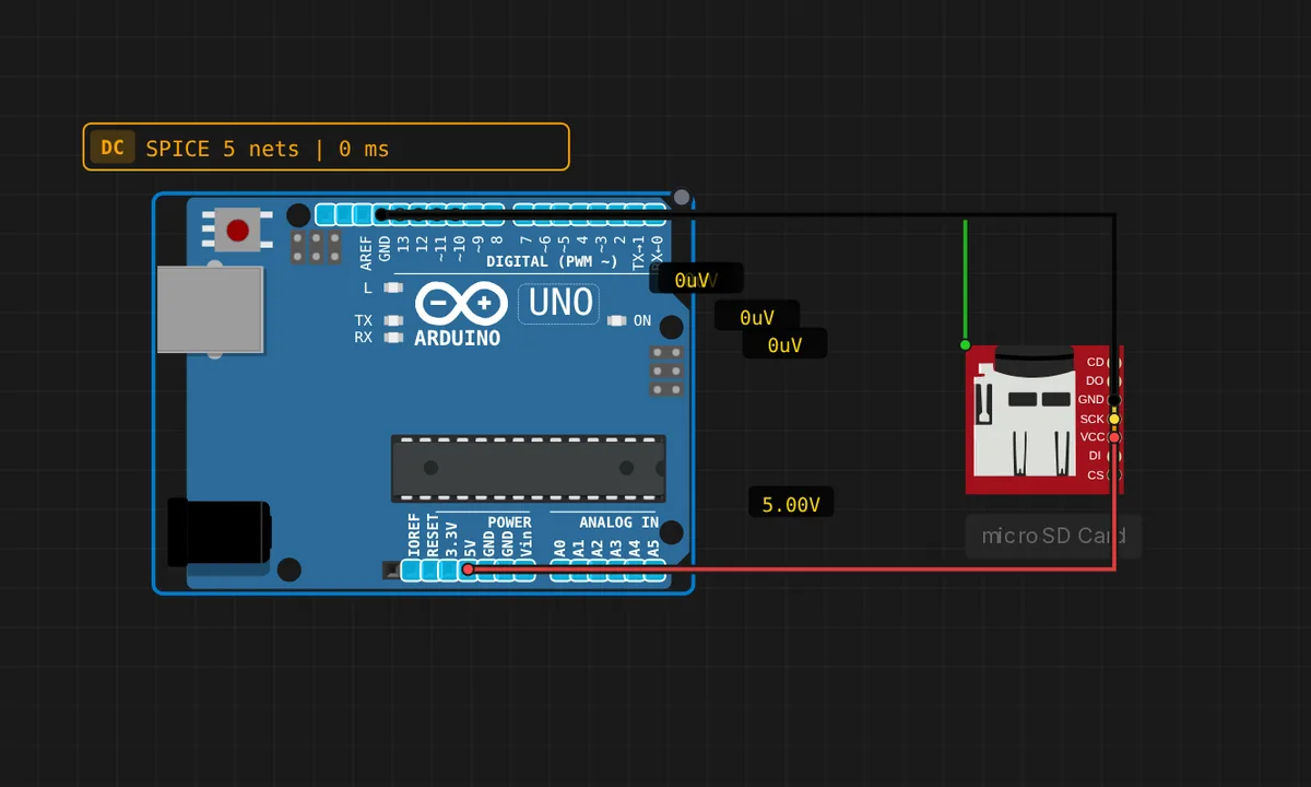
microSD Card (Arduino Uno)
Read and write files on a microSD card over SPI. The card is pre-loaded with this project's own files (free auto-copy); paid users can upload their own files from the component's "SD Card" panel. Lists the root directory, then writes /log.txt and reads it back. Open the Serial Monitor at 9600 baud.
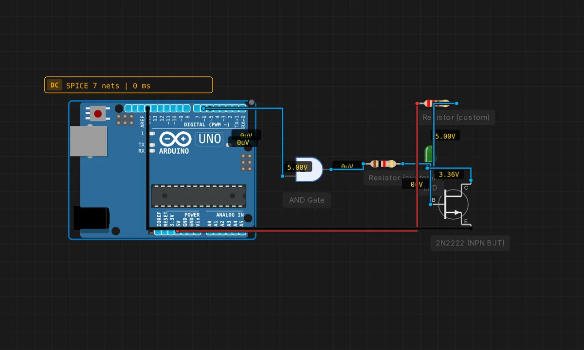
Mixed: MCU + AND gate + transistor (coexistence test)
Coexistence of digital and analog in ONE circuit: the Arduino drives two logic levels (one steady HIGH "enable", one blinking), a physical AND gate combines them, and the AND output switches an NPN transistor that drives the "motor" LED. The LED should blink — proving MCU -> logic gate -> transistor -> load works through the digital and analog (ngspice) motors together.
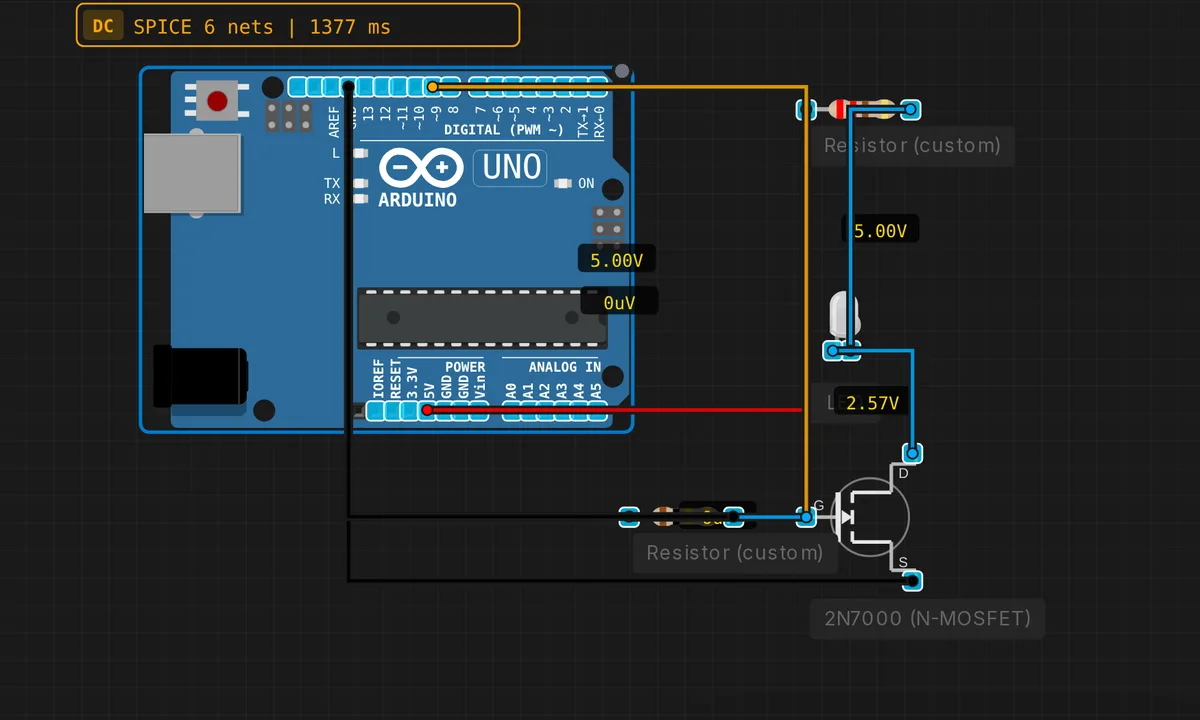
MOSFET PWM LED Dimmer
2N7000 N-MOSFET as low-side switch. Gate driven by PWM on pin 9 dims the LED.
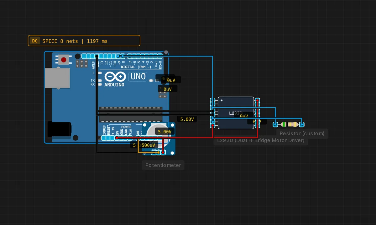
Motor Speed Control (PWM)
Potentiometer controls motor speed via PWM on L293D enable pin.
Multi-Protocol Demo
Uses Serial + I2C + SPI together. Reads RTC via I2C, sends SPI data, and logs everything to Serial.
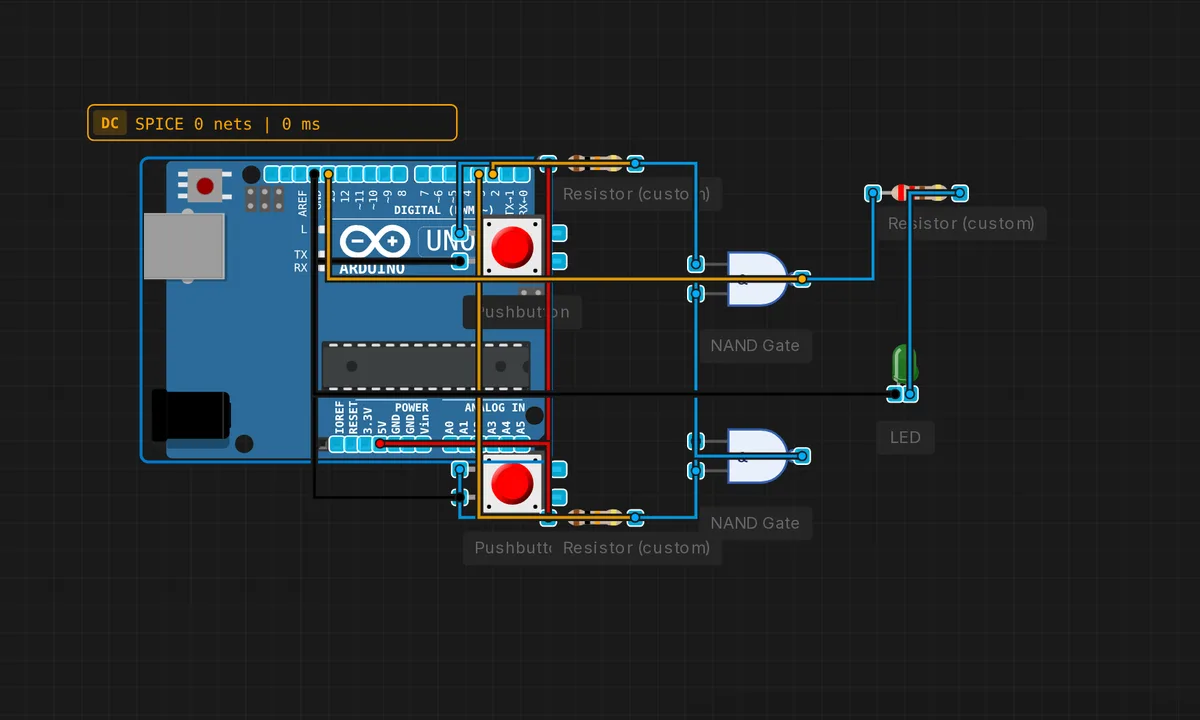
NAND SR Latch
Two cross-coupled NAND gates form a Set-Reset latch. Memory without a clock!
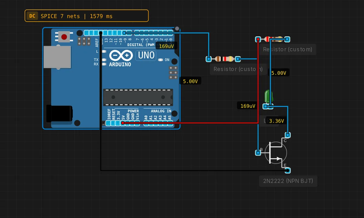
NPN Transistor LED Switch
2N2222 NPN switches a high-current LED from a low-current MCU pin.
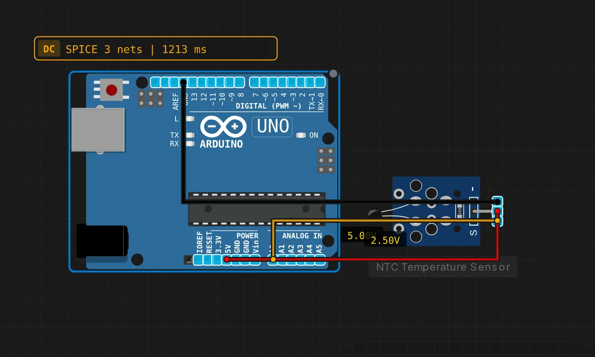
NTC Temperature Sensor
NTC breakout module (built-in 10k pull-up). Calculates temperature via beta model.
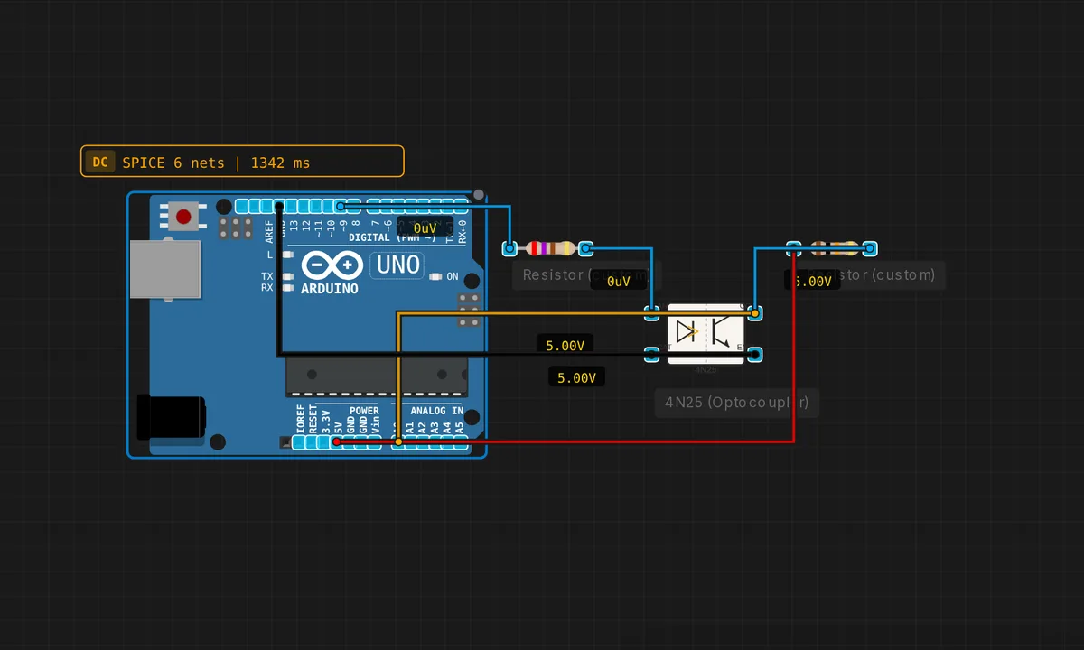
Optocoupler Signal Isolation
4N25 optocoupler isolates MCU from a higher-voltage circuit.
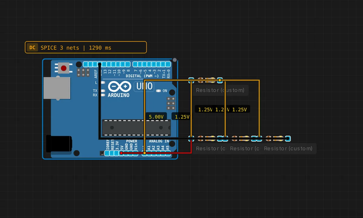
Parallel Resistors
Three resistors in parallel: R_total = 1/(1/R1+1/R2+1/R3). Measure with ADC.
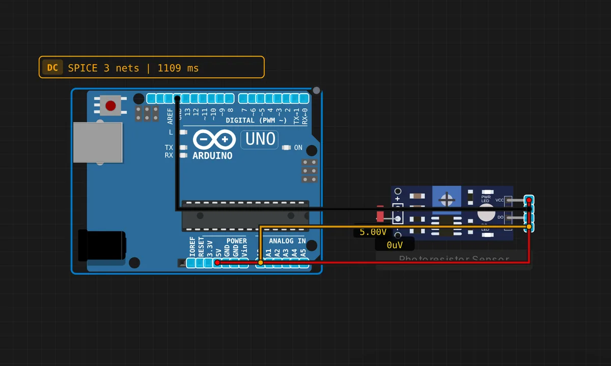
Photoresistor Light Sensor
LDR + pull-down resistor. Brighter light = lower LDR resistance = higher voltage.
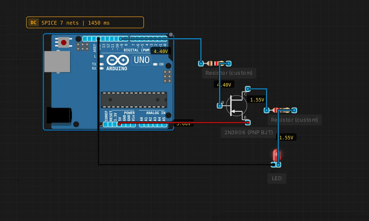
PNP High-Side Switch
2N3906 PNP switches a load to Vcc when base is pulled LOW.
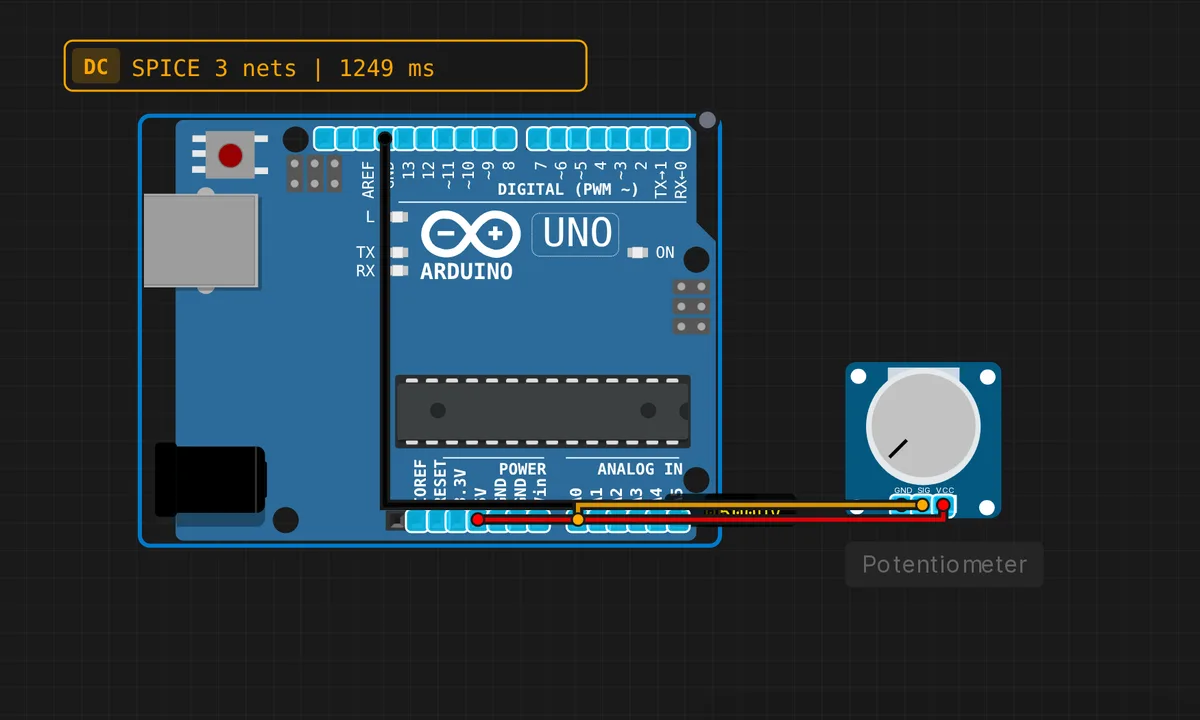
Potentiometer ADC Reader
Turn the potentiometer knob to vary the voltage on A0 from 0 to 5V.
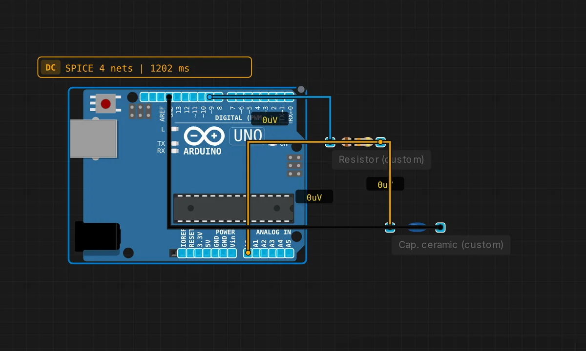
RC Low-Pass Filter
PWM output filtered by RC gives smooth analog voltage. Classic DAC trick.
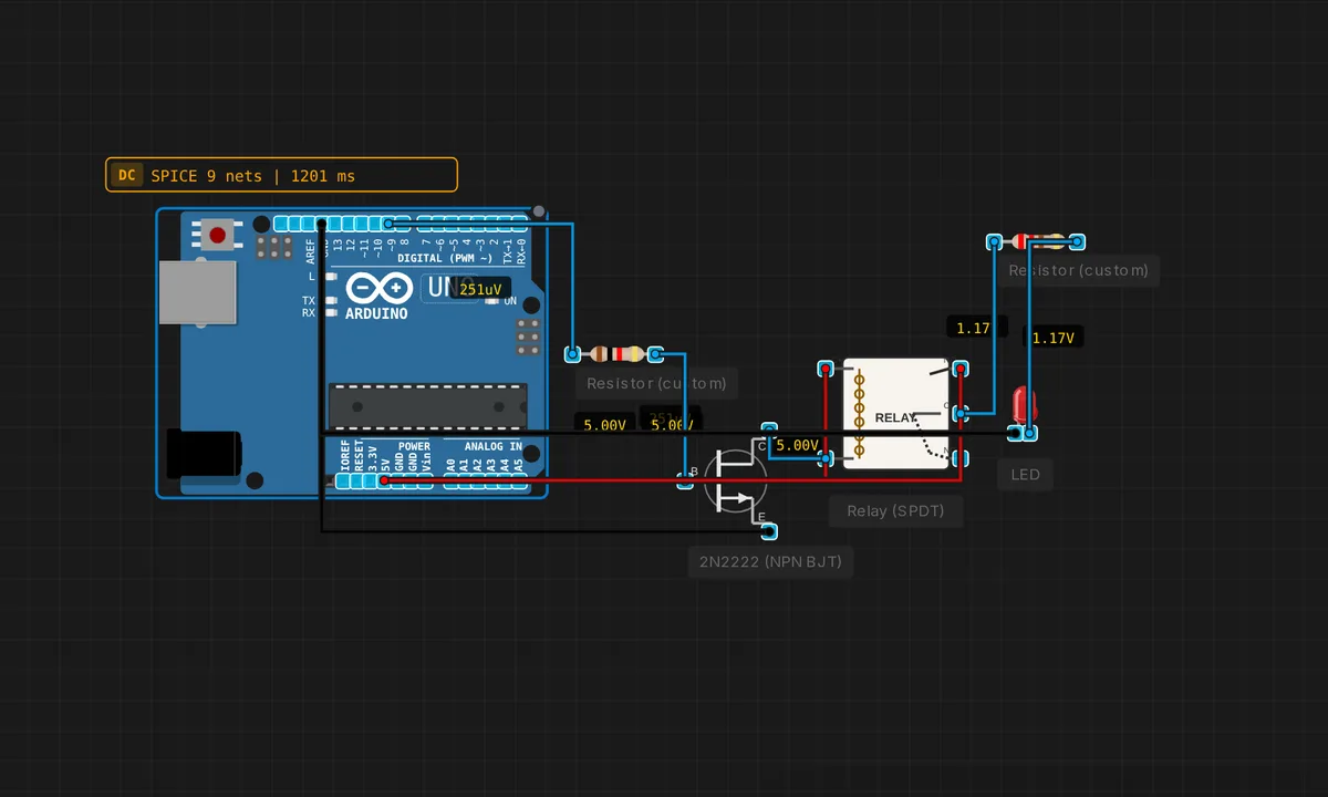
Relay-Controlled LED
NPN transistor drives a relay. Relay switches an LED connected to a separate supply.
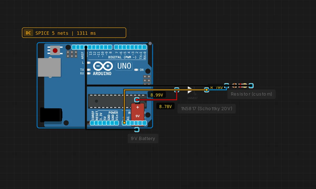
Reverse Polarity Protection
Schottky diode protects circuit from accidental reverse battery connection.
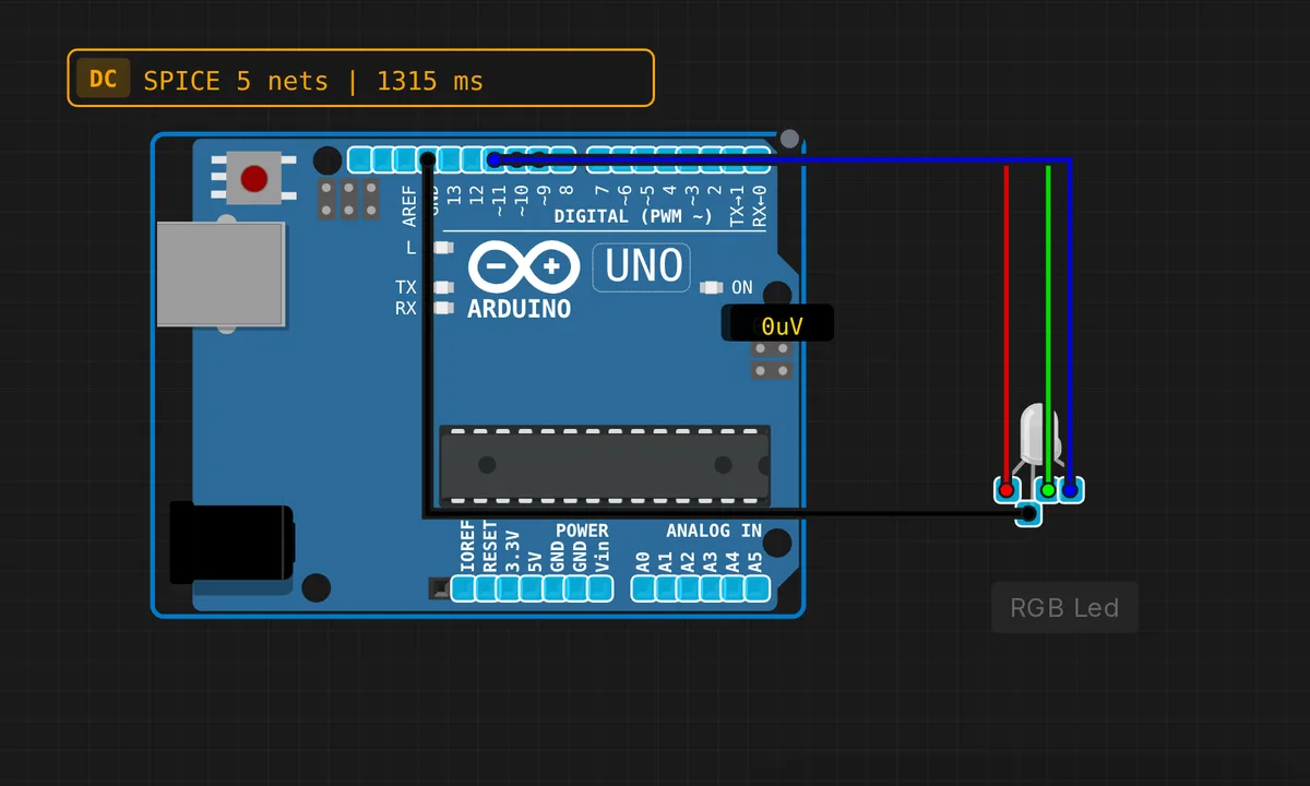
RGB LED Colors
Cycle through colors with an RGB LED
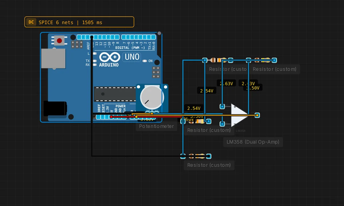
Schmitt Trigger
Op-amp with positive feedback creates hysteresis. Cleans up noisy signals.
Serial Echo (USART)
Tests Serial communication: echoes typed characters back and prints status. Open the Serial Monitor to interact.
Serial Hello World
Send messages through serial communication
Serial LED Control
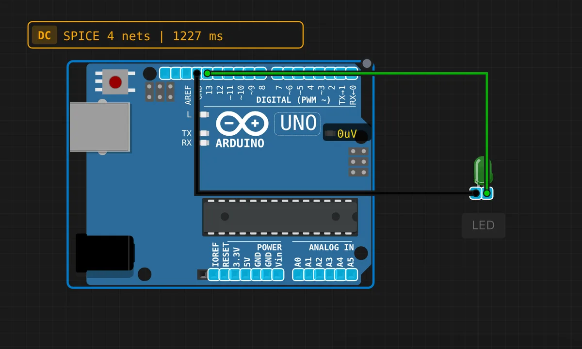
Control an LED via Serial commands: send "1" or "0". Tests USART RX + GPIO output together.
Simon Says Game
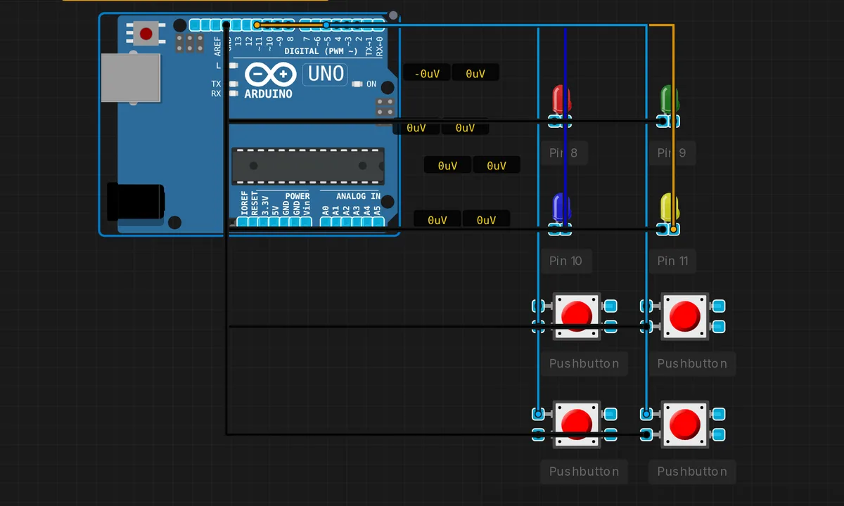
Memory game with LEDs and buttons
SPI Loopback Test
Tests SPI by sending bytes and reading responses. Demonstrates MOSI/MISO/SCK/SS protocol.
TFT ILI9341 Display
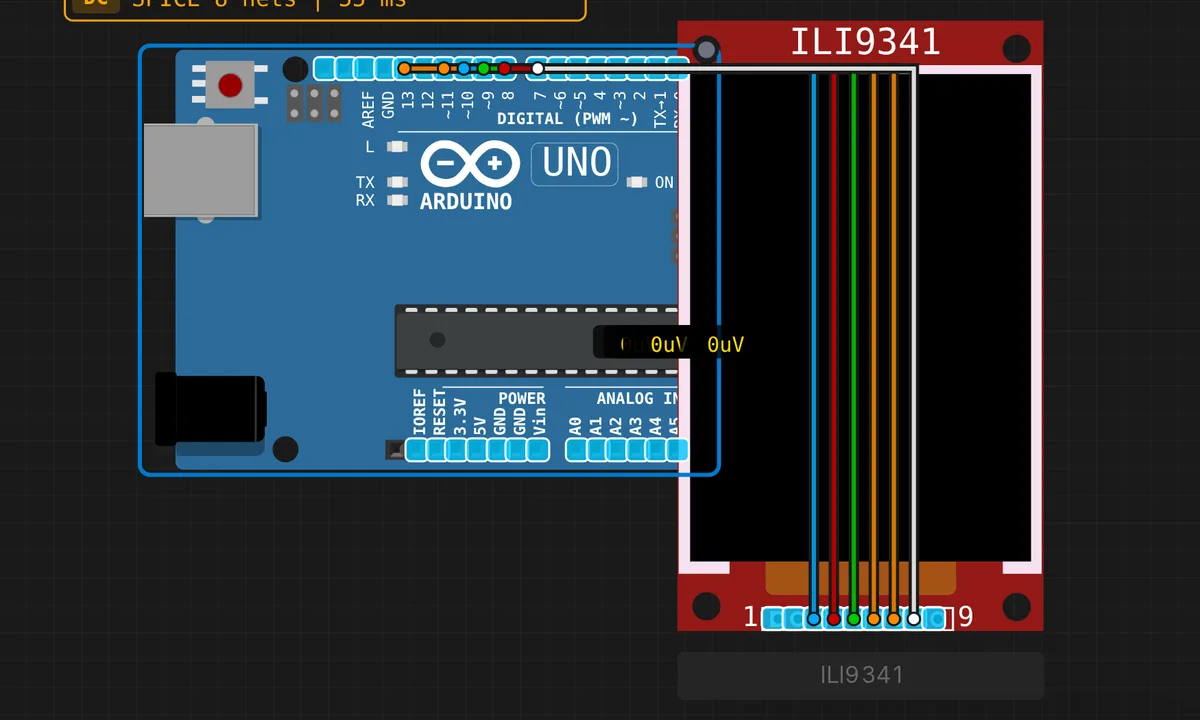
Color TFT display demo: fills, text, and a bouncing ball animation using the Adafruit ILI9341 library (240x320)
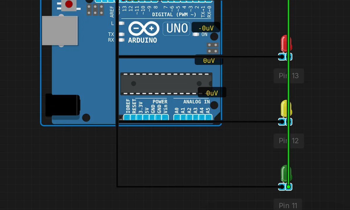
Traffic Light
Simulate a traffic light with red, yellow, and green LEDs
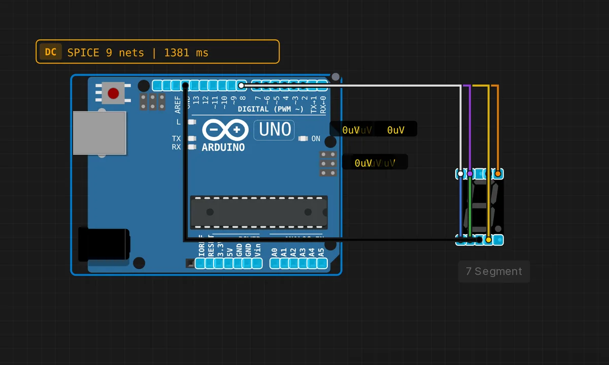
Uno: 7-Segment Counter
Count 0–9 on a 7-segment display driven directly from pins 2–8 on the Arduino Uno.
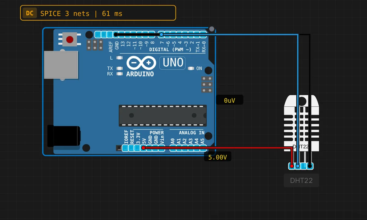
Uno: DHT22 Temperature & Humidity
Read temperature and humidity using a DHT22 sensor on pin 7.
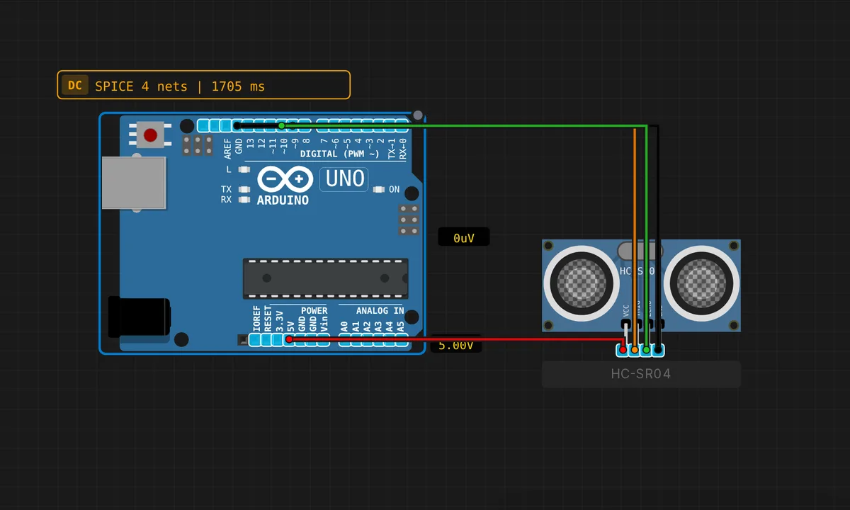
Uno: HC-SR04 Ultrasonic Distance
Measure distance with an HC-SR04 ultrasonic sensor. TRIG on pin 9, ECHO on pin 10.
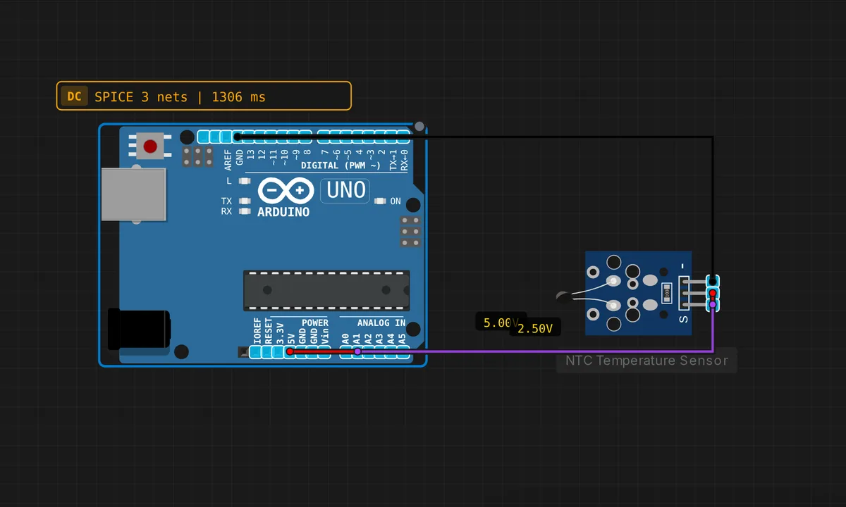
Uno: NTC Thermistor Temperature
Calculate temperature from an NTC 10k thermistor sensor on A1 using the Steinhart–Hart equation.
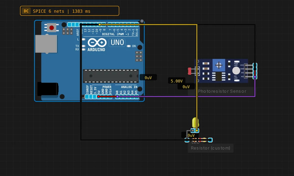
Uno: Photoresistor Light Sensor
Read analog light level from a photoresistor module on A0. An LED on pin 9 dims proportionally to compensate for darkness.
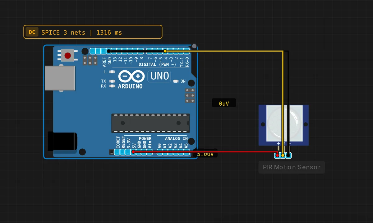
Uno: PIR Motion Detector
Detect movement with a PIR infrared sensor on pin 4. The built-in LED on pin 13 lights up when motion is detected.
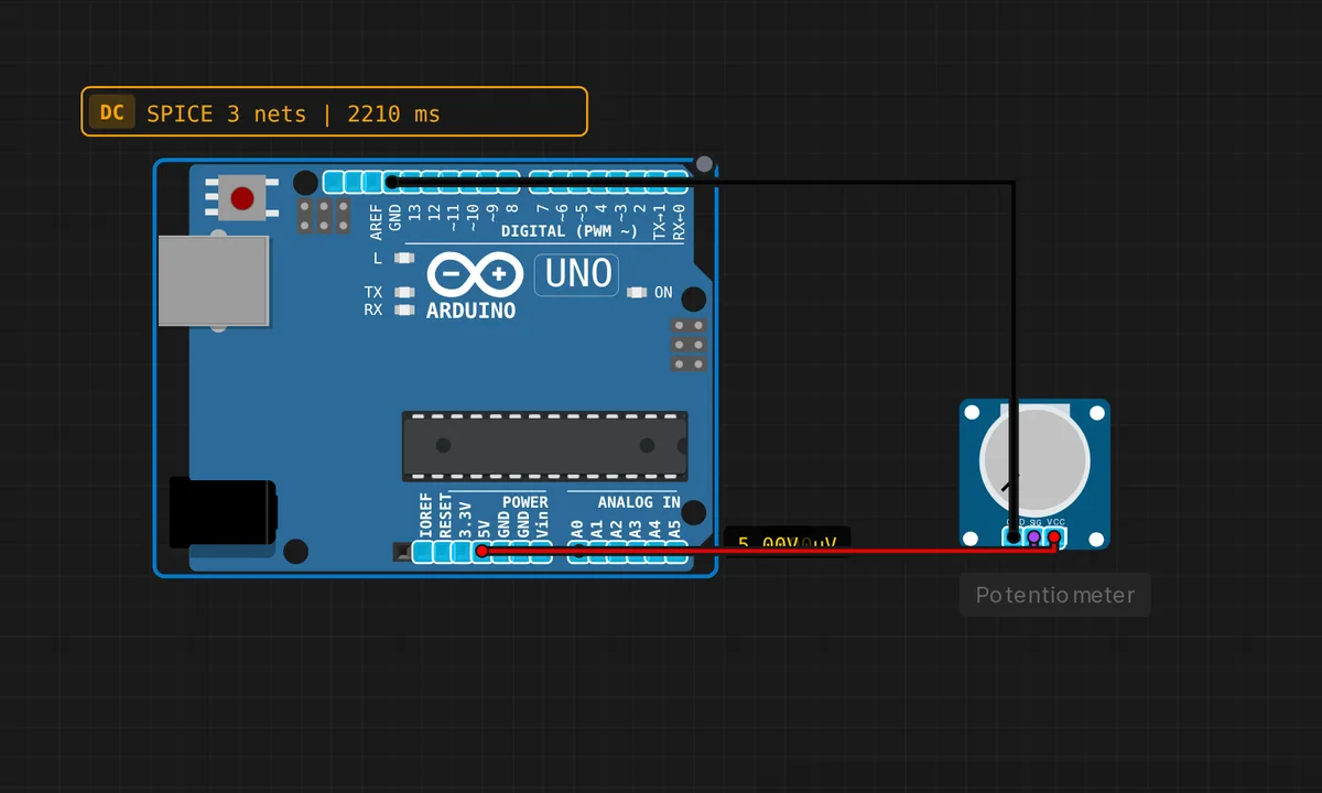
Uno: Potentiometer → Serial
Read an analog potentiometer on A0 and print the value to Serial Monitor.
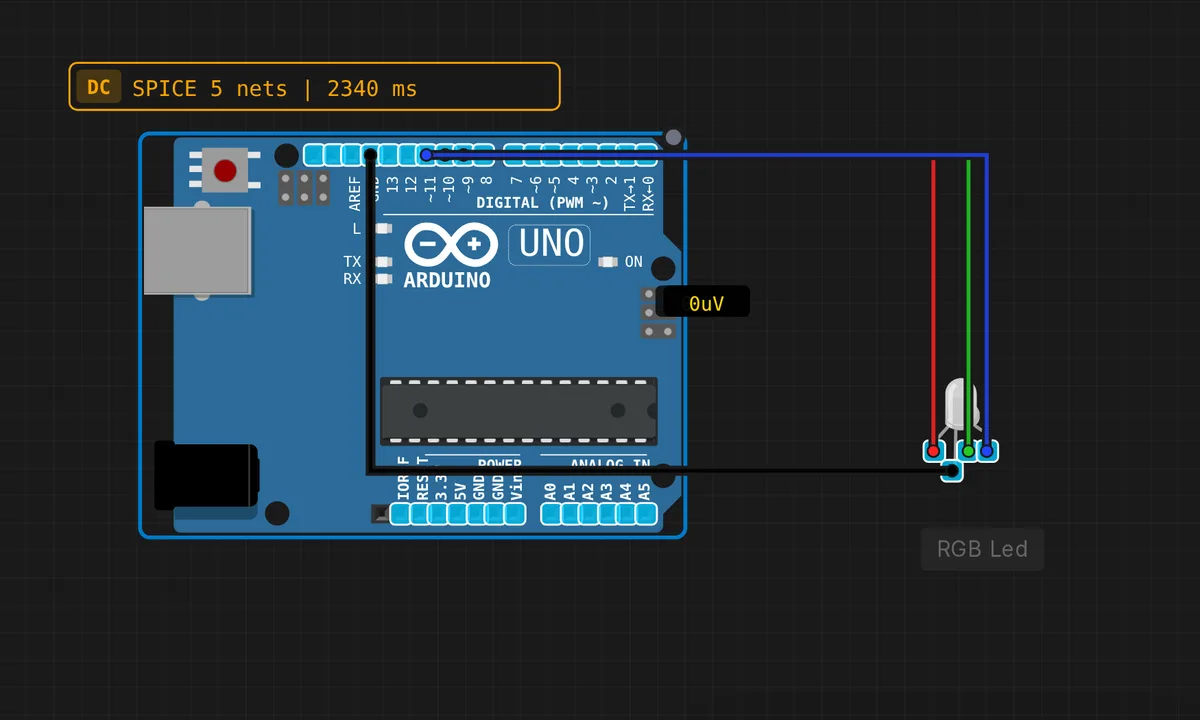
Uno: RGB LED Cycle
Cycle through 7 colors on an RGB LED connected to pins 9 (R), 10 (G), 11 (B) using PWM.
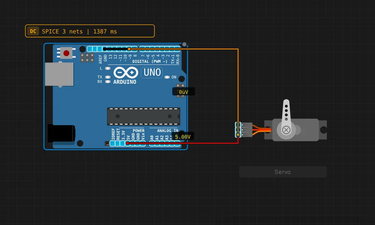
Uno: Servo Motor Sweep
Sweep a servo motor smoothly from 0° to 180° and back using pin 9 (PWM). Uses the built-in Servo library.
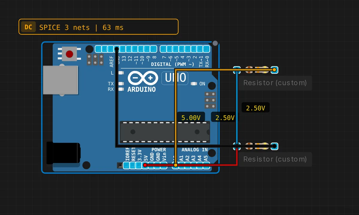
Voltage Divider
R1 + R2 divide 5V into a lower voltage read by ADC. Fundamental analog circuit.
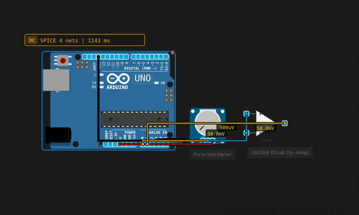
Voltage Follower (Buffer)
Op-amp with 100% feedback. Vout = Vin. High Z input, low Z output.
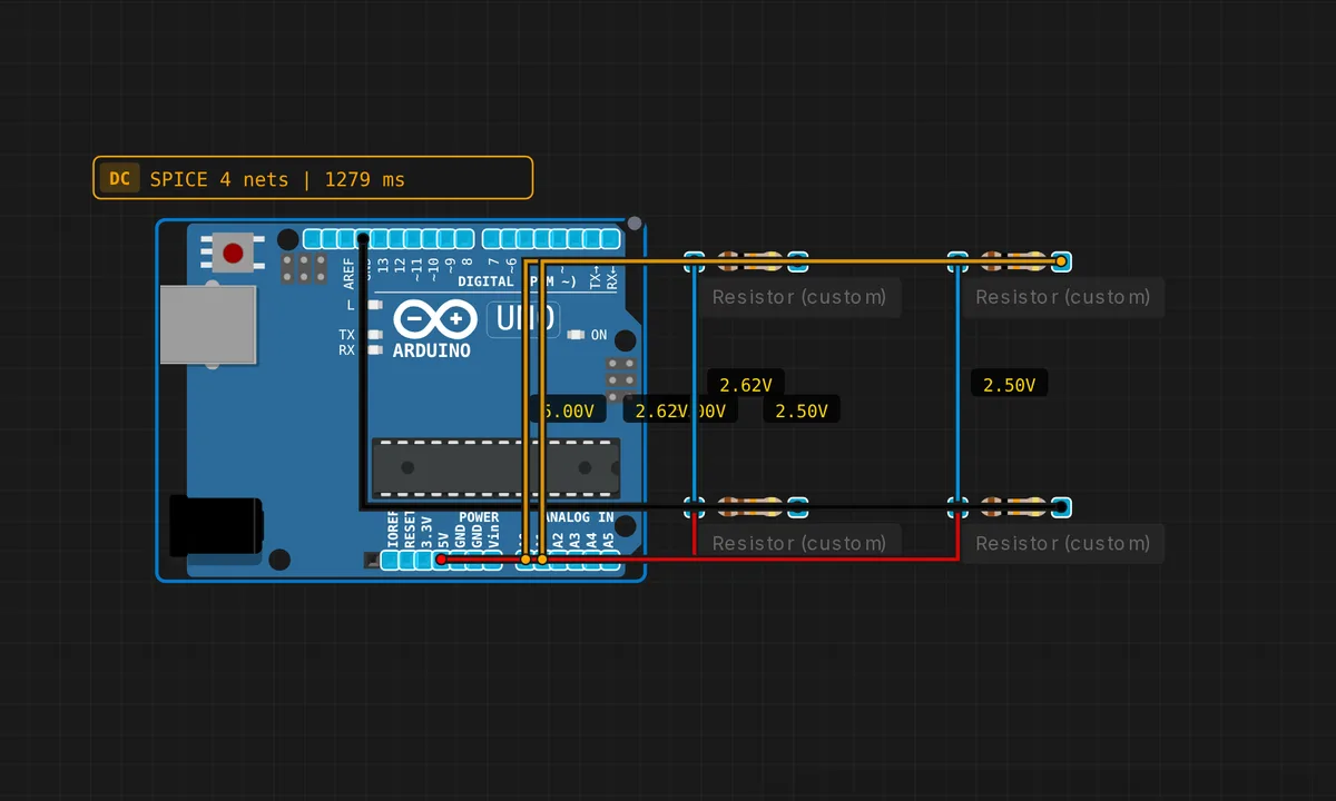
Wheatstone Bridge
Four-resistor bridge detects tiny resistance changes. Used in strain gauges and load cells.
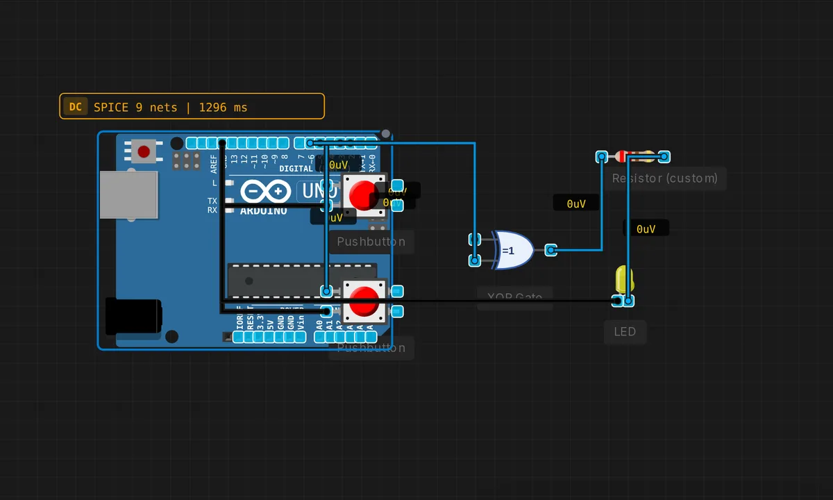
XOR Toggle Detector
XOR gate detects when two switches are in different positions.
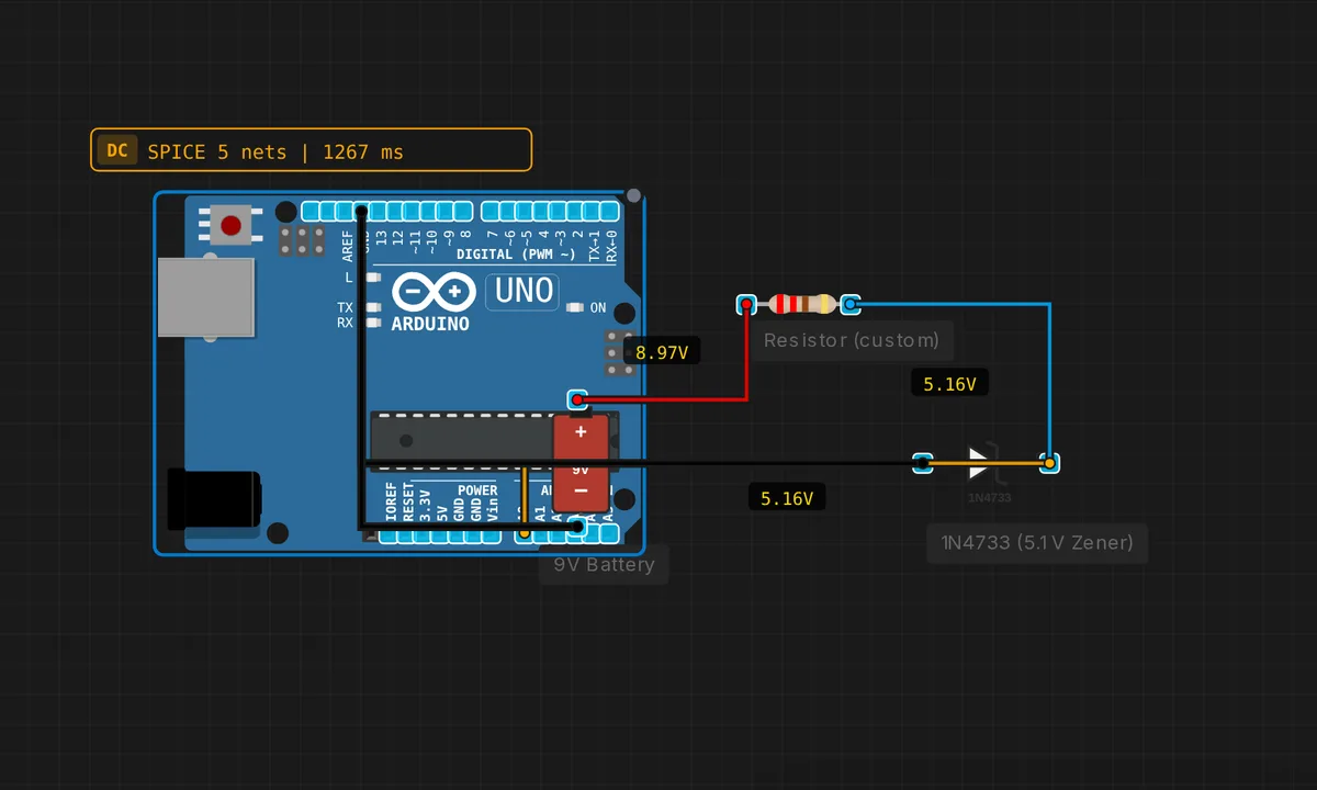
Zener Voltage Regulator
5.1V Zener clamps output. Even if input varies, output stays at 5.1V.
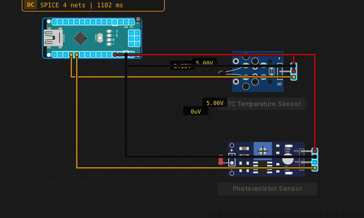
Arduino Nano Sensor Station
Compact weather station: NTC + photoresistor on Nano. Reads temp and light.
Nano: Blink LED
Blink the built-in LED on pin 13 of the Arduino Nano.
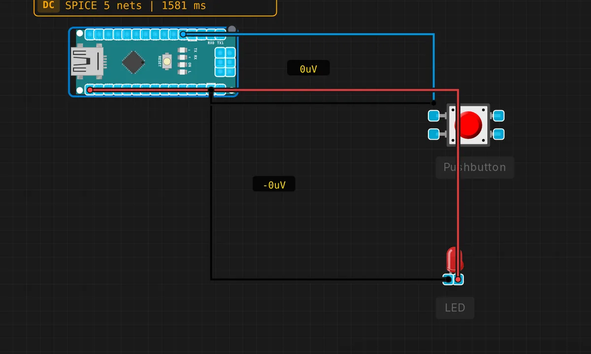
Nano: Button + LED
Press a button on pin 2 to light up an LED on pin 13 on the Arduino Nano.
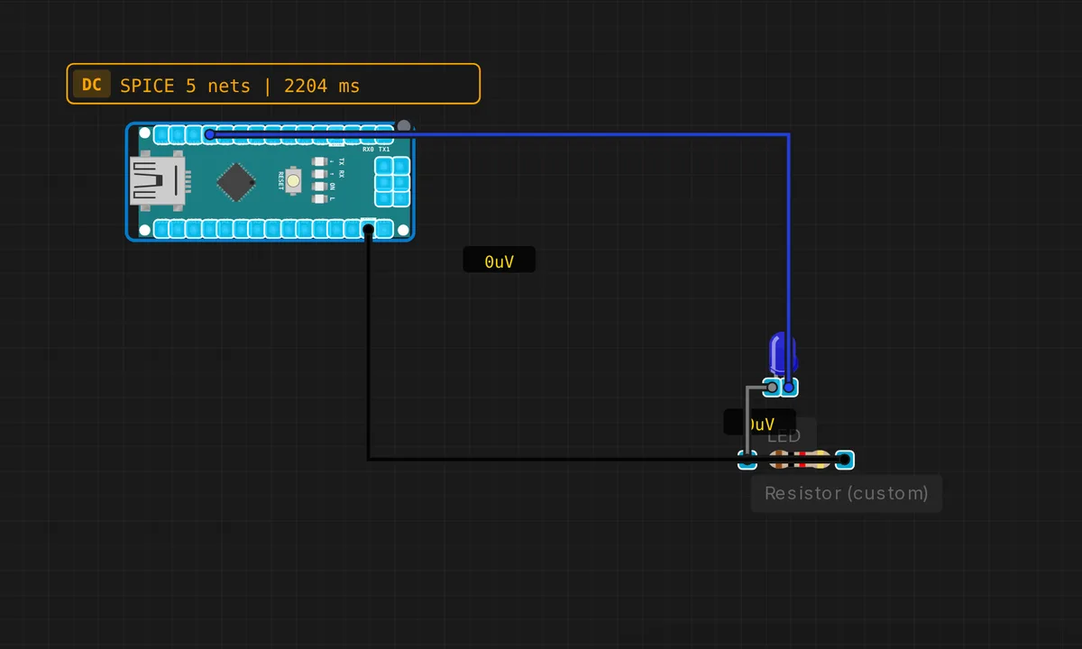
Nano: PWM Fade
Fade an LED in and out using PWM on pin 9 of the Arduino Nano.
Nano: Serial Hello
Print Hello World and uptime every second from Arduino Nano via Serial.
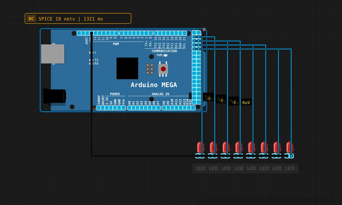
Arduino Mega 16-LED Bar
Arduino Mega drives 16 LEDs from pins 22-37. Knight Rider scanner effect.
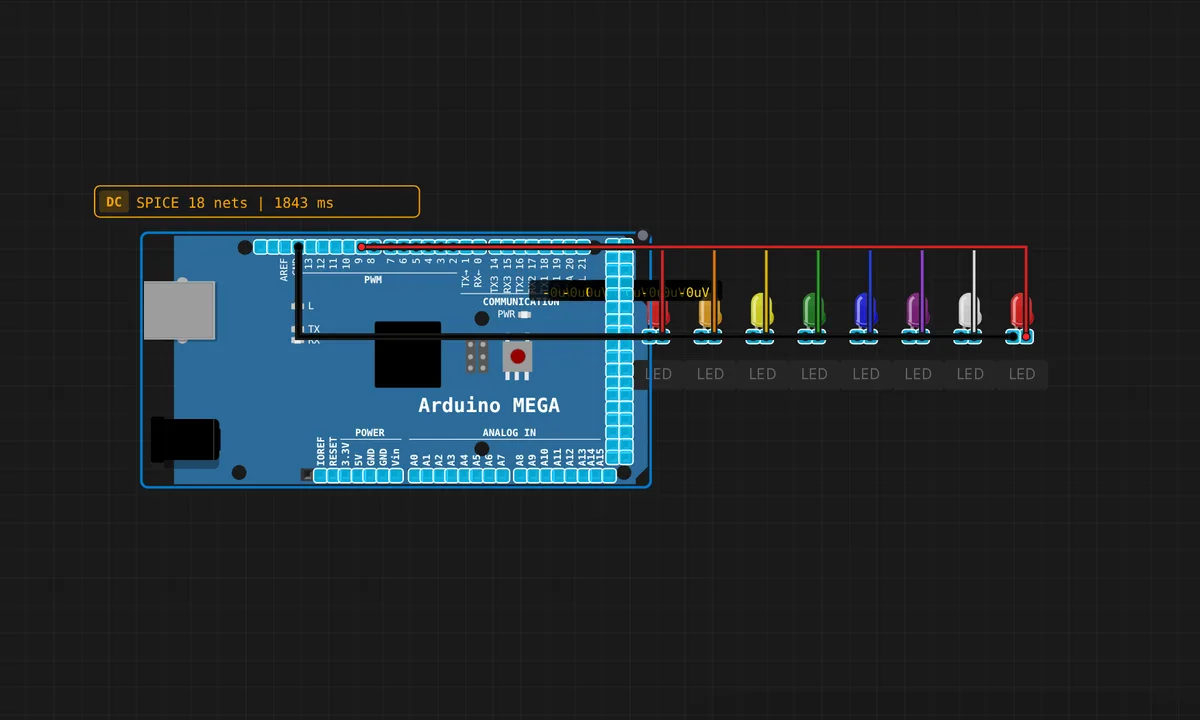
Mega: 8-LED Chase
Knight-Rider style LED chase across 8 LEDs on pins 2–9. Shows off the Mega's many I/O pins.
Mega: Blink LED
Blink the built-in LED on pin 13 of the Arduino Mega 2560.
Mega: Serial Hello
Hello World via Serial on Arduino Mega — tests all 4 UART ports.
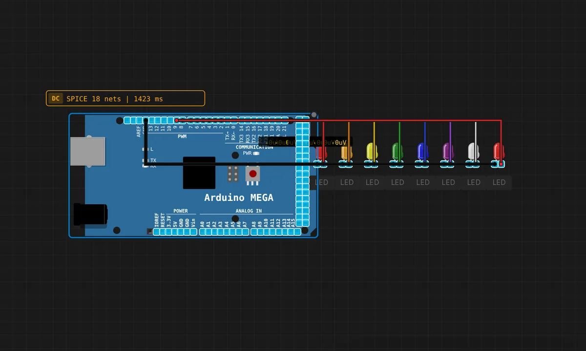
Mega: Serial LED Control
Send '1'–'8' over Serial to toggle individual LEDs on the Arduino Mega.
![[2× Pico W] Bidirectional Digital Handshake](/examples-thumbs/dual-pico-bidirectional-handshake.webp)
[2× Pico W] Bidirectional Digital Handshake
Two Picos signal each other over independent digital lines. Pico A drives GP15 (data) and watches GP14 (ack); Pico B reads GP15 and pulses GP14 on every transition to acknowledge. Each board's Serial Monitor logs every event, so you can see the round-trip on both sides.
![[2× Pico W] Digital GPIO Mirror](/examples-thumbs/dual-pico-digital-mirror.webp)
[2× Pico W] Digital GPIO Mirror
Simplest possible cross-board test. Pico A toggles GP15 every 500 ms; Pico B reads GP15 as a digital input and mirrors its state to its built-in LED. Watch each Pico's Serial Monitor to confirm the wire is alive.
![[2× Pico W] Serial1 Passthrough (UART0)](/examples-thumbs/dual-pico-serial1-passthrough.webp)
[2× Pico W] Serial1 Passthrough (UART0)
Two Raspberry Pi Pico W boards talking over Serial1 (UART0 on GP0/GP1). Pico A sends "PING #N" every second; Pico B replies "PONG #N". Open the Serial Monitor on each board to see the conversation.
![[Pico] ADC Read](/examples-thumbs/pico-adc-read.webp)
[Pico] ADC Read
Read analog values from GPIO26-28 and internal temperature sensor
![[Pico] Blink LED](/examples-thumbs/pico-blink.webp)
[Pico] Blink LED
Classic blink example on Raspberry Pi Pico — GPIO25 built-in LED
![[Pico] I2C EEPROM R/W](/examples-thumbs/pico-i2c-eeprom-rw.webp)
[Pico] I2C EEPROM R/W
Write and read back data to a virtual I2C EEPROM on the Pico
![[Pico] I2C RTC Read](/examples-thumbs/pico-i2c-rtc-read.webp)
[Pico] I2C RTC Read
Read time from a virtual DS1307 RTC over I2C on Raspberry Pi Pico
![[Pico] I2C Scanner](/examples-thumbs/pico-i2c-scanner.webp)
[Pico] I2C Scanner
Scan the I2C bus on the Pico for connected devices
![[Pico] Multi-Protocol Demo](/examples-thumbs/pico-multi-protocol.webp)
[Pico] Multi-Protocol Demo
Comprehensive test: Serial + I2C + SPI + ADC on the Raspberry Pi Pico
![[Pico] Serial Echo](/examples-thumbs/pico-serial-echo.webp)
[Pico] Serial Echo
Echo serial input back with a timestamp — tests UART on RP2040
![[Pico] Serial LED Control](/examples-thumbs/pico-serial-led-control.webp)
[Pico] Serial LED Control
Control the Pico LED via serial commands (1=ON, 0=OFF, ?=status)
![[Pico] SPI Loopback](/examples-thumbs/pico-spi-loopback.webp)
[Pico] SPI Loopback
SPI loopback test on RP2040 — sends and receives bytes via SPI0
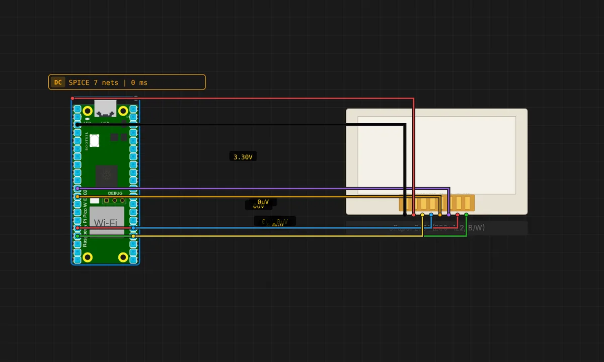
ePaper 2.13" Wall Clock — Raspberry Pi Pico
Counts seconds and refreshes the framebuffer once per minute on a 2.13" 250×122 SSD1675A panel. Runs on the Pico via the Earle Philhower core; SPI0 default pins.
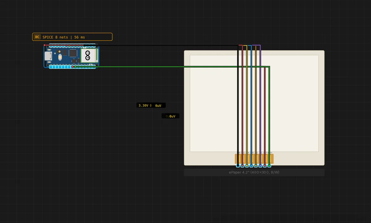
ePaper 4.2" Static Image — Raspberry Pi Pico
Embeds a fixed 400×300 black-and-white pattern (concentric squares) and pushes it once. Big enough to demonstrate a real layout — title block, divider, data table.
Joystick Direction Display with OLED
Joystick Direction Display with OLED on Raspberry Pi Pico (MicroPython) — uses OLED. From Kritish Mohapatra's 100 Days of IoT series: https://github.com/kritishmohapatra/100_Days_100_IoT_Projects
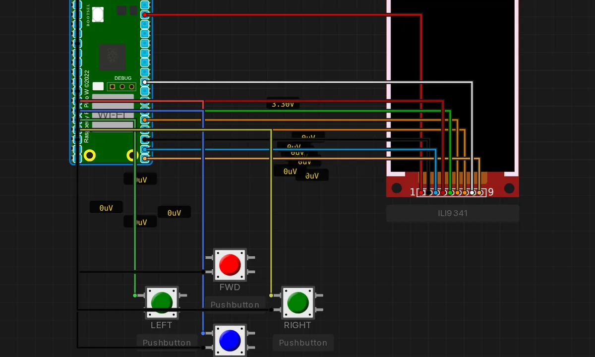
Pico Doom — Raycaster Demo
Wolfenstein / early-Doom-style first-person 3D corridor on a Pi Pico + ILI9341 TFT. DDA raycasting at 160 rays/frame, no framebuffer (columns drawn straight to the TFT via drawFastVLine). Forward/back move, two more buttons turn the player. 16×16 tile map with 5 wall palettes (slate, blood, brown, toxic green, bronze door). The full id Software Doom needs the WAD assets shoehorned into 2 MB of flash with custom compression that the emulator cannot reproduce — this is the visual demo the Pico hardware actually runs in real life.
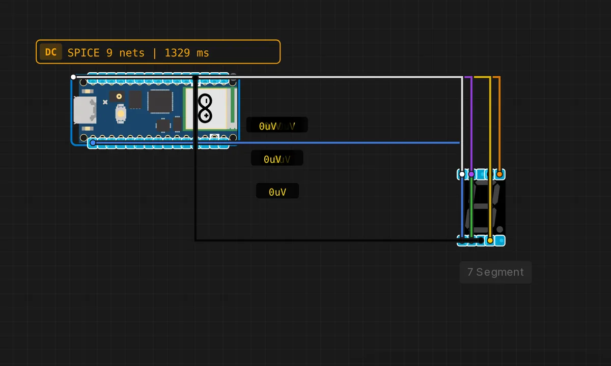
Pico: 7-Segment Counter
Count 0–9 on a 7-segment display driven from GPIO 2–8 on the Raspberry Pi Pico.
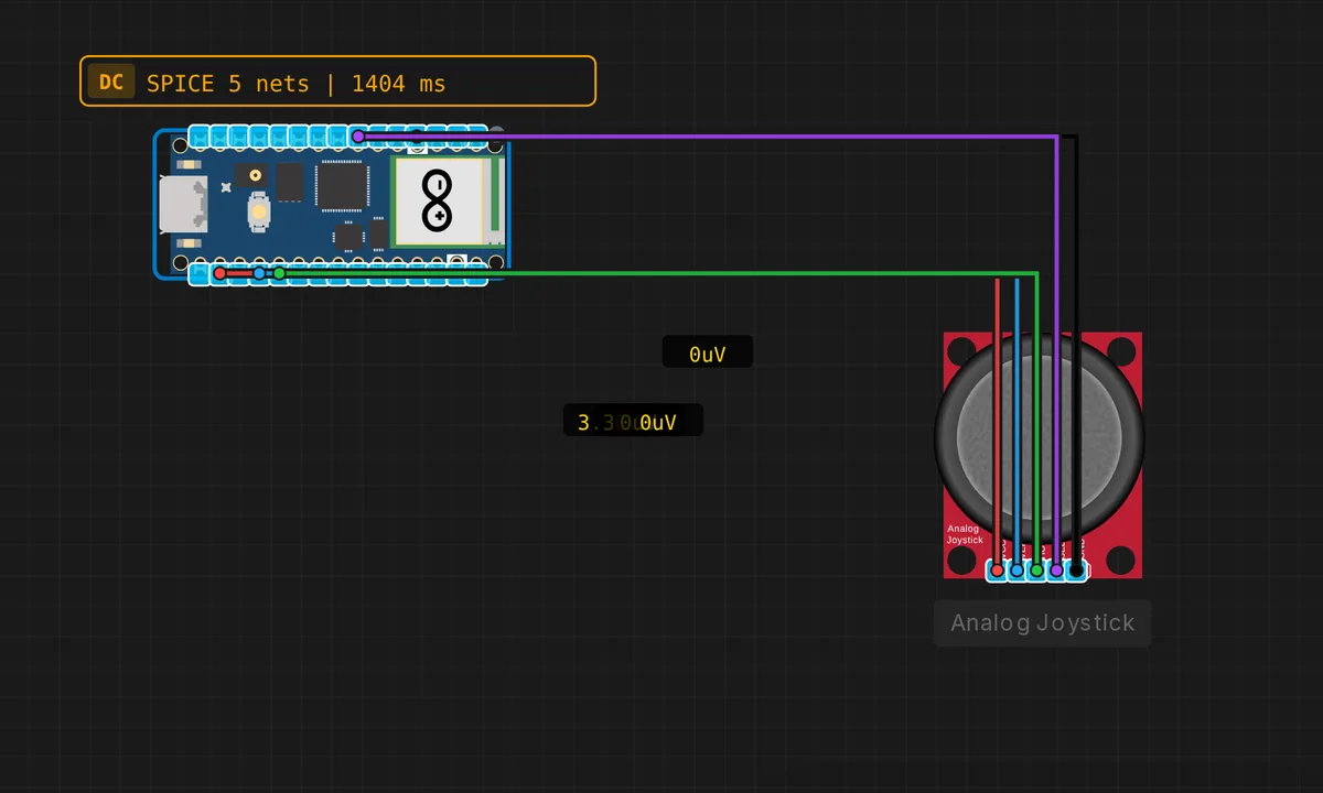
Pico: Analog Joystick
Read X/Y axes and button press from an analog joystick. VERT on A0 (GP26), HORZ on A1 (GP27), SEL button on D4 (GP16).
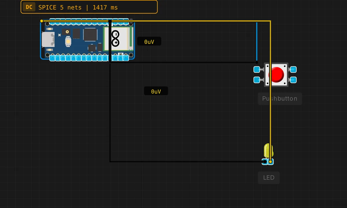
Pico: Button + LED
Press a button on GP2 to light up an LED on GP3 on the Raspberry Pi Pico.
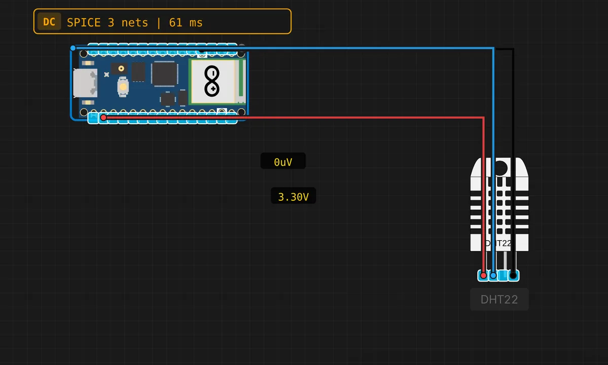
Pico: DHT22 Temperature & Humidity
Read temperature and humidity from a DHT22 sensor on GP7 using the Raspberry Pi Pico.
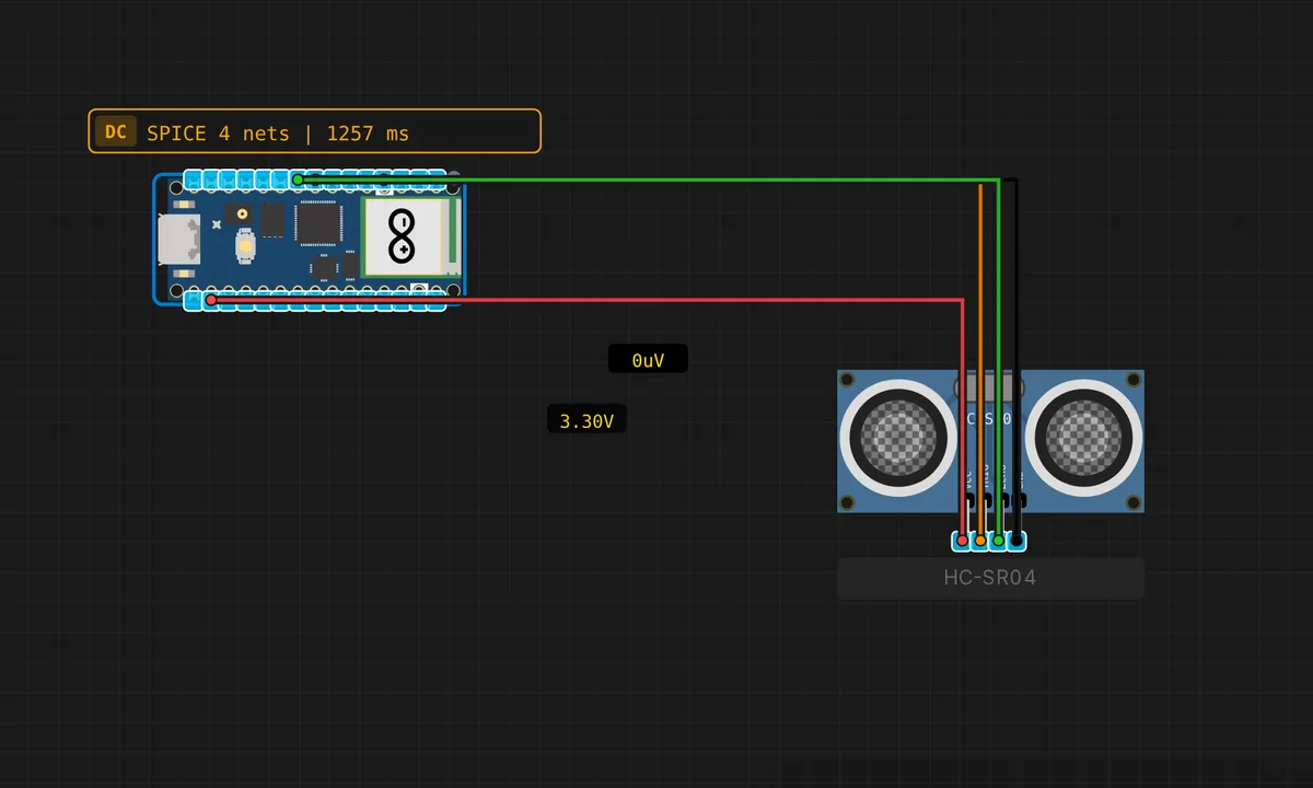
Pico: HC-SR04 Ultrasonic Distance
Measure distance with an HC-SR04 sensor on the Raspberry Pi Pico. TRIG on D5 (GP17), ECHO on D6 (GP18).
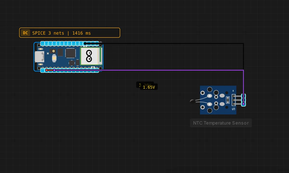
Pico: NTC Thermistor Temperature
Read temperature from an NTC 10k thermistor on the Pico ADC pin A0 (GP26) using the Steinhart–Hart equation.
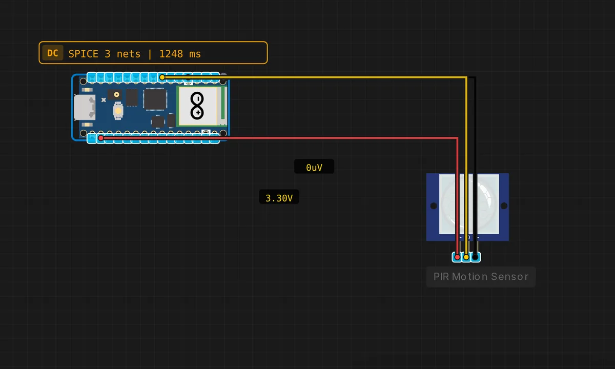
Pico: PIR Motion Detector
Detect movement with a PIR sensor on D4 (GP16). The built-in LED (GP25) activates when motion is detected.
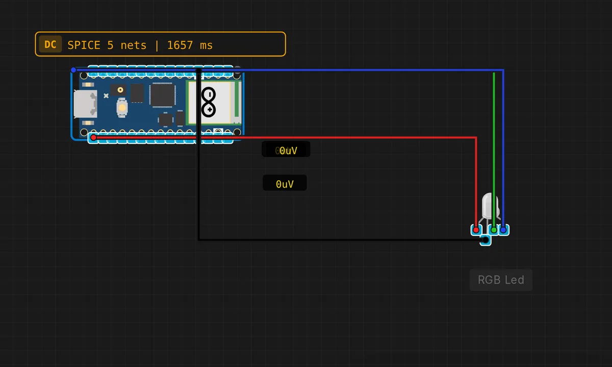
Pico: RGB LED Cycle
Cycle through colors on an RGB LED using GPIO 6 (R), 7 (G), 8 (B) on the Raspberry Pi Pico.
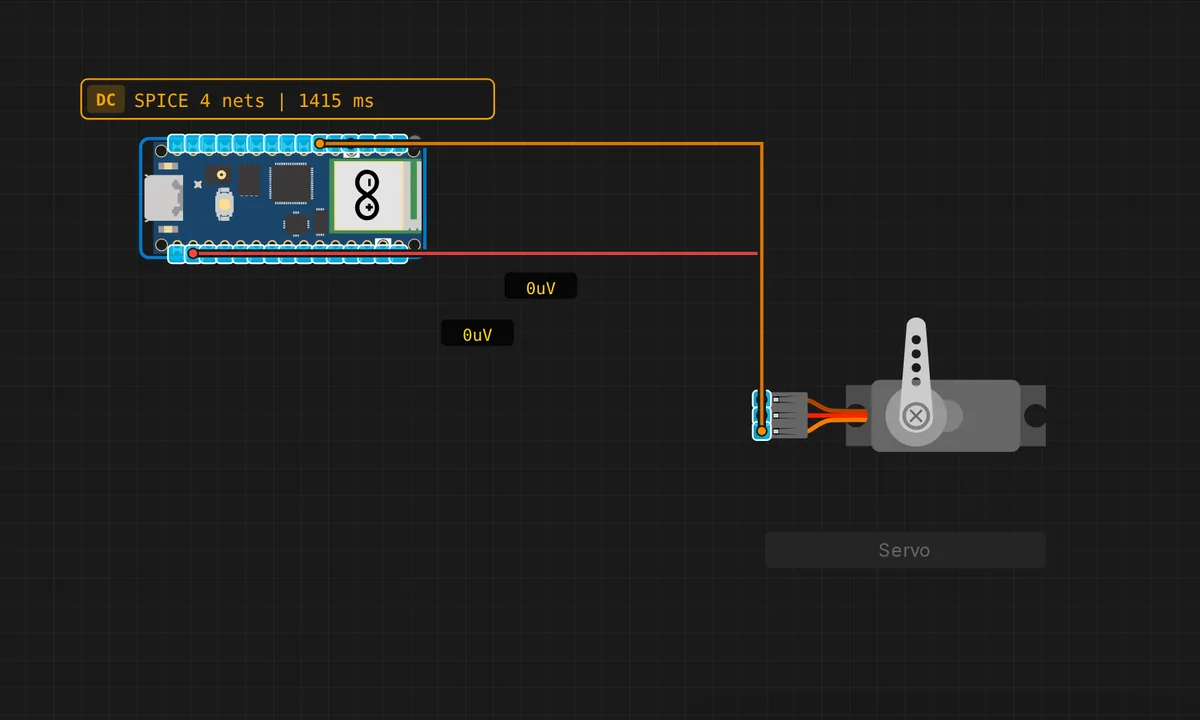
Pico: Servo Motor Sweep
Sweep a servo motor from 0° to 180° and back on the Raspberry Pi Pico using D3 / GP15 (PWM).
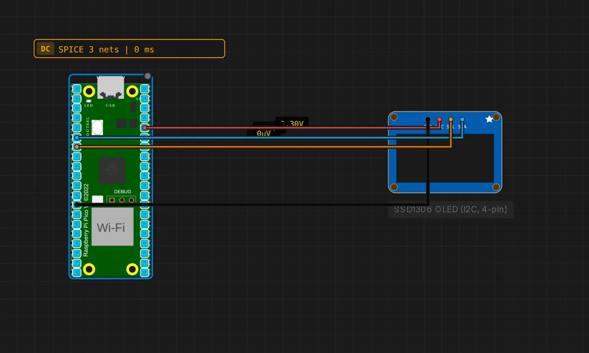
Raspberry Pi Pico: SSD1306 OLED (4-pin I2C)
Drive the cheap 4-pin SSD1306 OLED module (GND/VCC/SCL/SDA) over I2C from a Raspberry Pi Pico (SDA=GP4, SCL=GP5).
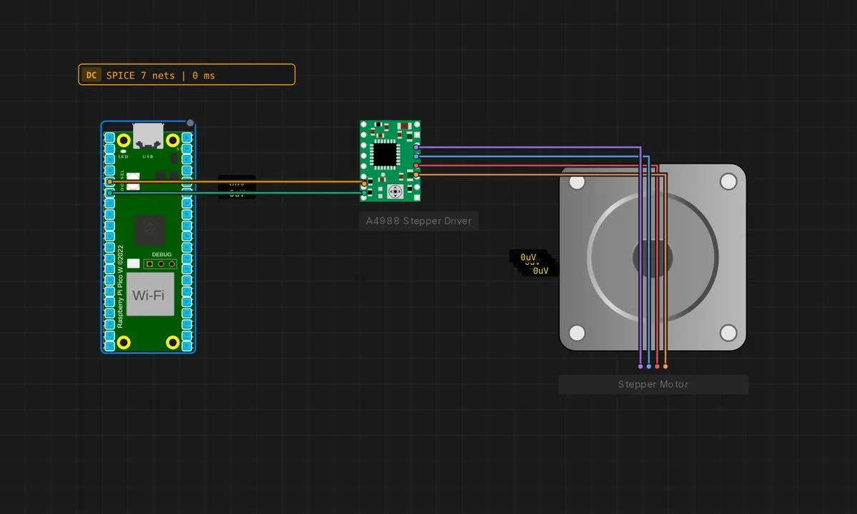
Raspberry Pi Pico: Stepper + A4988
Spin a bipolar stepper motor from a Raspberry Pi Pico through an A4988 driver (STEP = GP3, DIR = GP4).
Single Digit Seven Segment Display with Raspberry Pi-Pico (MicroPython)
Single Digit Seven Segment Display with Raspberry Pi-Pico (MicroPython) on Raspberry Pi Pico (MicroPython). From Kritish Mohapatra's 100 Days of IoT series: https://github.com/kritishmohapatra/100_Days_100_IoT_Projects
Blynk Based IoT Relay Control (MicroPython)
Blynk Based IoT Relay Control (MicroPython) on Raspberry Pi Pico W (MicroPython) — uses Blynk, Blynk Cloud, Wi-Fi. From Kritish Mohapatra's 100 Days of IoT series: https://github.com/kritishmohapatra/100_Days_100_IoT_Projects
IoT Relay Control Web Server (Raspberry Pi Pico 2W)
IoT Relay Control Web Server (Raspberry Pi Pico 2W) on Raspberry Pi Pico W (MicroPython) — uses Wi-Fi. From Kritish Mohapatra's 100 Days of IoT series: https://github.com/kritishmohapatra/100_Days_100_IoT_Projects
OTA Update Pico2W
OTA Update Pico2W on Raspberry Pi Pico W (MicroPython) — uses OTA, Wi-Fi. From Kritish Mohapatra's 100 Days of IoT series: https://github.com/kritishmohapatra/100_Days_100_IoT_Projects
Pico 2 W Dht11 Http Csv Logger
Pico 2 W Dht11 Http Csv Logger on Raspberry Pi Pico W (MicroPython) — uses DHT, HTTP server, Wi-Fi. From Kritish Mohapatra's 100 Days of IoT series: https://github.com/kritishmohapatra/100_Days_100_IoT_Projects
Pico W Async LED Control (MicroPython)
Pico W Async LED Control (MicroPython) on Raspberry Pi Pico W (MicroPython) — uses Wi-Fi. From Kritish Mohapatra's 100 Days of IoT series: https://github.com/kritishmohapatra/100_Days_100_IoT_Projects
Pico W Web Servo Controller
Pico W Web Servo Controller on Raspberry Pi Pico W (MicroPython) — uses OTA, Servo, Wi-Fi. From Kritish Mohapatra's 100 Days of IoT series: https://github.com/kritishmohapatra/100_Days_100_IoT_Projects
PIR Motion Detector using Raspberry Pi Pico 2W & MicroPython
PIR Motion Detector using Raspberry Pi Pico 2W & MicroPython on Raspberry Pi Pico W (MicroPython). From Kritish Mohapatra's 100 Days of IoT series: https://github.com/kritishmohapatra/100_Days_100_IoT_Projects
Raspberry Pi Pico 2 W ThingsBoard IoT
Raspberry Pi Pico 2 W ThingsBoard IoT on Raspberry Pi Pico W (MicroPython) — uses DHT, MQTT, Wi-Fi. From Kritish Mohapatra's 100 Days of IoT series: https://github.com/kritishmohapatra/100_Days_100_IoT_Projects
Servo Motor Control with Raspberry Pi Pico 2 W (MicroPython)
Servo Motor Control with Raspberry Pi Pico 2 W (MicroPython) on Raspberry Pi Pico W (MicroPython) — uses Servo. From Kritish Mohapatra's 100 Days of IoT series: https://github.com/kritishmohapatra/100_Days_100_IoT_Projects
WebSocket LED Control using Raspberry Pi Pico W
WebSocket LED Control using Raspberry Pi Pico W on Raspberry Pi Pico W (MicroPython) — uses WebSocket, Wi-Fi. From Kritish Mohapatra's 100 Days of IoT series: https://github.com/kritishmohapatra/100_Days_100_IoT_Projects
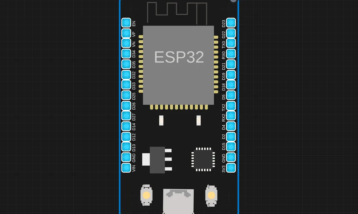
AQI ESP
AQI ESP on ESP32 (MicroPython) — uses DHT, HTTP server, OLED, Wi-Fi. From Kritish Mohapatra's 100 Days of IoT series: https://github.com/kritishmohapatra/100_Days_100_IoT_Projects
Auto Night Light using LDR (ESP32 + MicroPython)
Auto Night Light using LDR (ESP32 + MicroPython) on ESP32 (MicroPython) — uses LDR. From Kritish Mohapatra's 100 Days of IoT series: https://github.com/kritishmohapatra/100_Days_100_IoT_Projects
Battery Monitor with Blynk IoT
Battery Monitor with Blynk IoT on ESP32 (MicroPython) — uses Blynk, Blynk Cloud, Wi-Fi. From Kritish Mohapatra's 100 Days of IoT series: https://github.com/kritishmohapatra/100_Days_100_IoT_Projects
Bluetooth Based Wireless LED Control System
Bluetooth Based Wireless LED Control System on ESP32 (MicroPython) — uses BLE. From Kritish Mohapatra's 100 Days of IoT series: https://github.com/kritishmohapatra/100_Days_100_IoT_Projects
Blynk Controlled DC Brushless Fan
Blynk Controlled DC Brushless Fan on ESP32 (MicroPython) — uses Blynk, Blynk Cloud, Wi-Fi. From Kritish Mohapatra's 100 Days of IoT series: https://github.com/kritishmohapatra/100_Days_100_IoT_Projects
Clap Toggle Switch using ESP32 & Digital Sound Sensor (MicroPython)
Clap Toggle Switch using ESP32 & Digital Sound Sensor (MicroPython) on ESP32 (MicroPython). From Kritish Mohapatra's 100 Days of IoT series: https://github.com/kritishmohapatra/100_Days_100_IoT_Projects
DC Motor Speed Control (Web Slider)
DC Motor Speed Control (Web Slider) on ESP32 (MicroPython) — uses Servo, Wi-Fi. From Kritish Mohapatra's 100 Days of IoT series: https://github.com/kritishmohapatra/100_Days_100_IoT_Projects
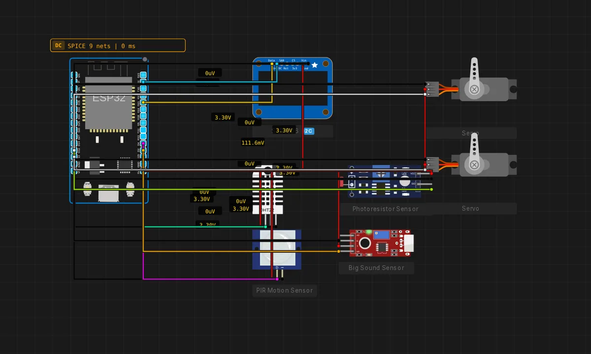
Desktop Robot — Animated Eyes
Cozmo-style desktop robot on ESP32: OLED face with random blinks/looks/expressions, DHT11 weather mode, PIR-triggered wakeup, LDR sleep when dark, sound-triggered reactions and two eyebrow servos. 34-file C++ project, real Arduino libraries (U8g2lib, DHT, ESP32Servo).

DHT11 Web Server using ESP32 & MicroPython
DHT11 Web Server using ESP32 & MicroPython on ESP32 (MicroPython) — uses DHT, Wi-Fi. From Kritish Mohapatra's 100 Days of IoT series: https://github.com/kritishmohapatra/100_Days_100_IoT_Projects
Dimmer LED using Potentiometer (MicroPython)
Dimmer LED using Potentiometer (MicroPython) on ESP32 (MicroPython) — uses Servo. From Kritish Mohapatra's 100 Days of IoT series: https://github.com/kritishmohapatra/100_Days_100_IoT_Projects
Dual IR Entry Exit Detector with Telegram Alerts
Dual IR Entry Exit Detector with Telegram Alerts on ESP32 (MicroPython) — uses Telegram, Wi-Fi. From Kritish Mohapatra's 100 Days of IoT series: https://github.com/kritishmohapatra/100_Days_100_IoT_Projects
EEPROM Simulation using MicroPython on ESP32 (Wokwi)
EEPROM Simulation using MicroPython on ESP32 (Wokwi) on ESP32 (MicroPython). From Kritish Mohapatra's 100 Days of IoT series: https://github.com/kritishmohapatra/100_Days_100_IoT_Projects
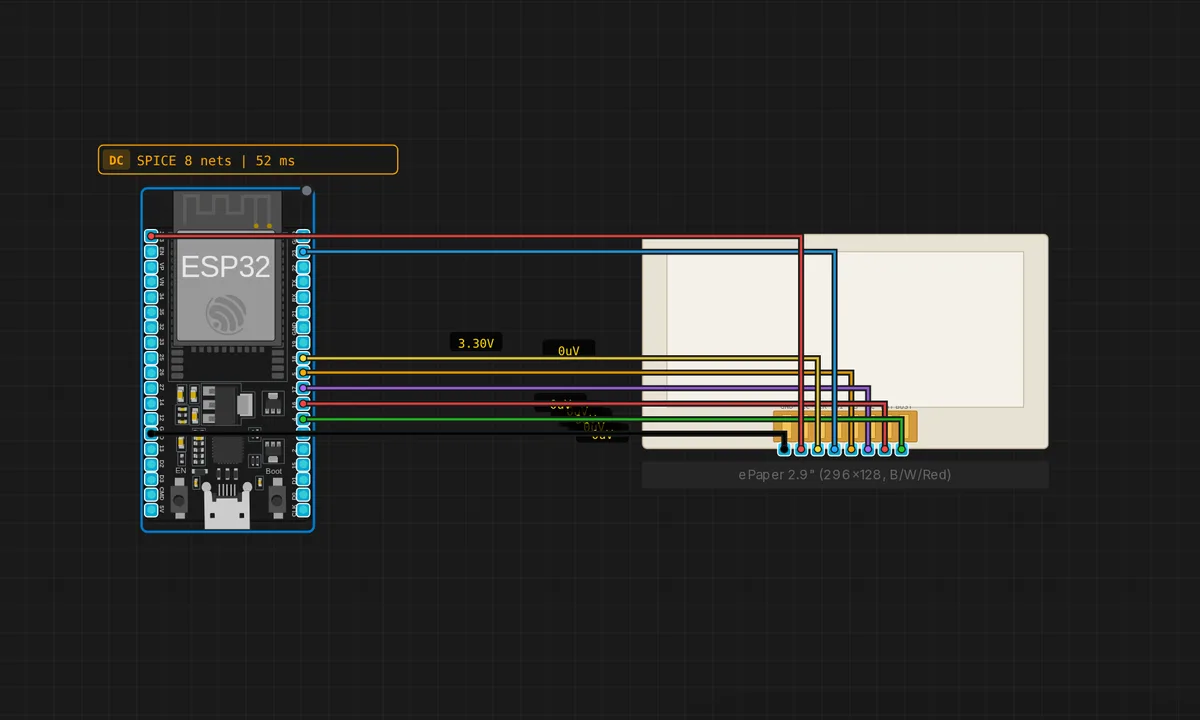
ePaper 2.9" Tri-Colour Alert — ESP32
Tri-colour 296×128 B/W/Red panel showing a status badge. Demonstrates the SSD1680 red plane: title in black, "ALERT" pill in red on white. Exercises both 0x24 (BW) and 0x26 (Red) RAM commands.
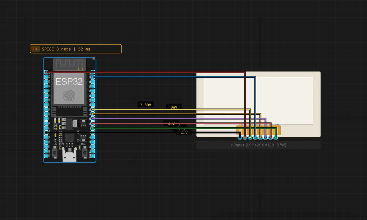
ePaper 2.9" Weather — ESP32
Mock weather widget on a 2.9" 296×128 SSD1680 panel. Demonstrates ePaper rendering via the backend Ssd168xEpaperSlave — the QEMU worker decodes SPI traffic and ships the latched frame back to the browser as an `epaper_update` WebSocket event.
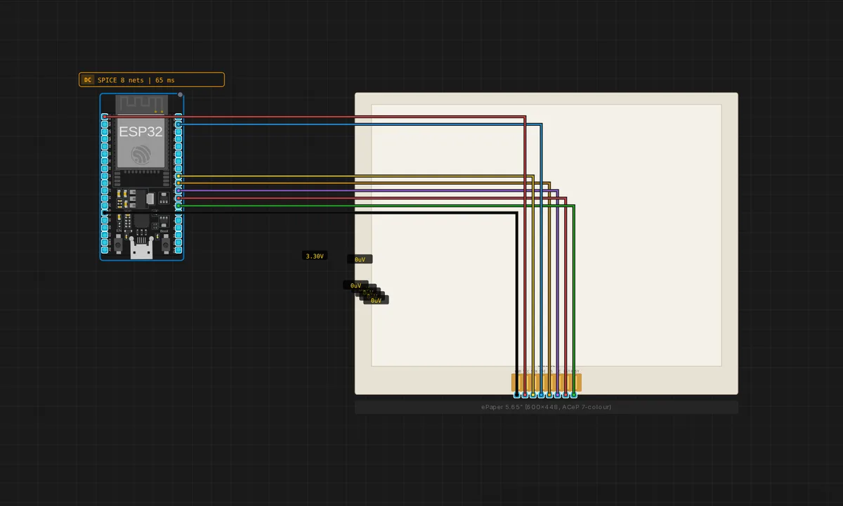
ePaper 5.65" 7-colour Rainbow — ESP32
Drives the GoodDisplay GDEP0565D90 / Waveshare 5.65" ACeP 7-colour panel (UC8159c controller). Renders horizontal colour bars + a centred title to show every palette entry. Real-hardware refresh is ~12 s; the emulator pulses BUSY for 150 ms.
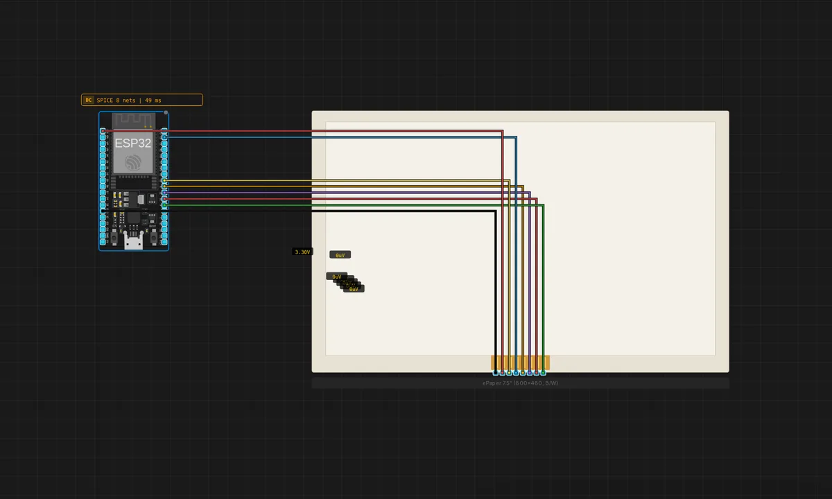
ePaper 7.5" Dashboard — ESP32
Full 800×480 multi-tile dashboard on the largest mono panel. ESP32 only — the framebuffer is too big for AVR/Pico flash with paged GxEPD2.
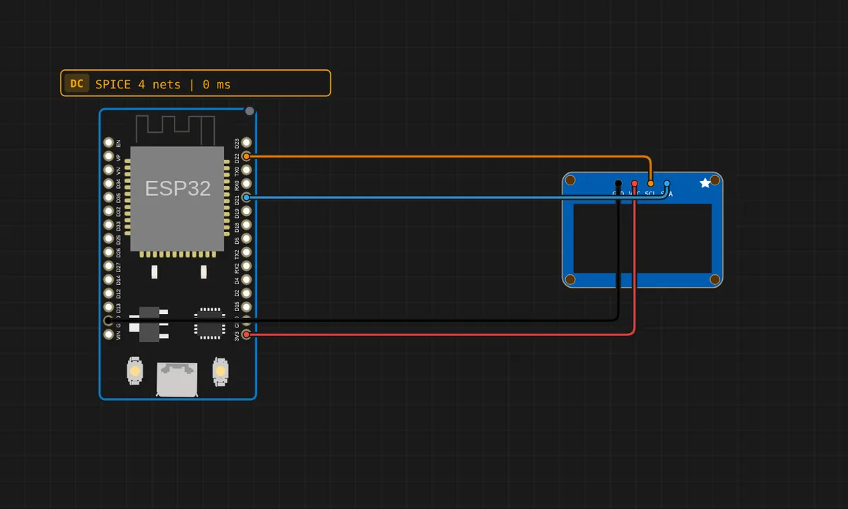
ESP32 + MicroPython: use an external library
How a MicroPython project uses a library in Velxio: there is no requirements.txt and no package manager — the driver is a .py file in the workspace. Every file here is copied onto the board's filesystem before main.py runs, so `import ssd1306` picks up the ssd1306.py next to it and draws on the wired OLED. The toolbar's Library Manager installs ARDUINO libraries and has no effect in MicroPython mode.
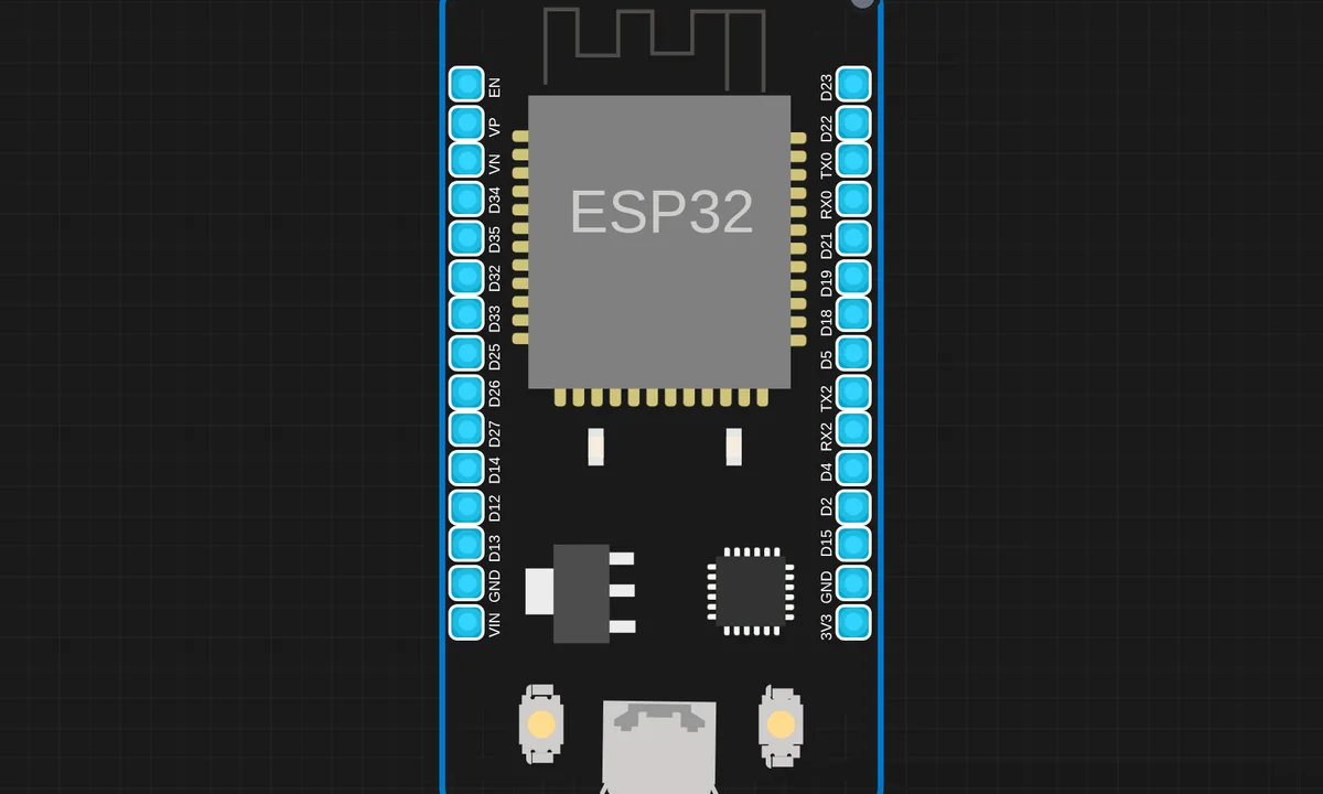
ESP32 BLE Advertise
Initialize BLE and start advertising. Note: BLE initialization is detected but actual BLE communication is not emulated in the current simulator.
ESP32 BLE LED Control
ESP32 BLE LED Control on ESP32 (MicroPython) — uses BLE. From Kritish Mohapatra's 100 Days of IoT series: https://github.com/kritishmohapatra/100_Days_100_IoT_Projects
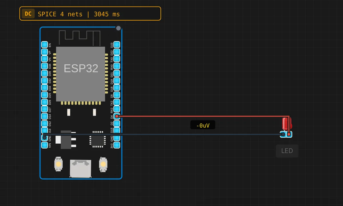
ESP32 Blink LED
Blink the built-in LED on GPIO2 and an external red LED on GPIO4. Verifies ESP32 emulation is working.
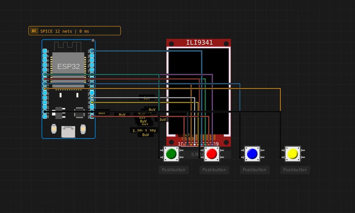
ESP32 Doom — Raycaster (ILI9341)
A Wolfenstein / early-Doom style first-person raycaster on an ESP32 + ILI9341 320x240 colour TFT. The whole screen is redrawn every frame over hardware SPI (VSPI) with Adafruit_ILI9341 block writes (one startWrite/endWrite burst per frame), plus distance fog and darker E/W faces for depth. Four buttons move and turn the player; an auto-demo walks the 16x16 map when idle. Built as an emulation-speed benchmark — it overlays the on-device FPS and prints frame/FPS stats over Serial.
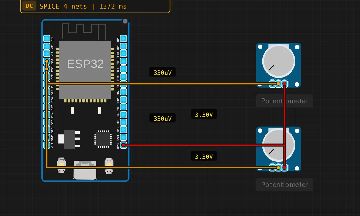
ESP32 Dual ADC Reader
ESP32 reads two analog channels (GPIO34, GPIO35) simultaneously at 12-bit resolution.
ESP32 Hotspot (Access Point) Setup MicroPython
ESP32 Hotspot (Access Point) Setup MicroPython on ESP32 (MicroPython) — uses Wi-Fi. From Kritish Mohapatra's 100 Days of IoT series: https://github.com/kritishmohapatra/100_Days_100_IoT_Projects
ESP32 HTTP Server
Run a simple web server on the ESP32. After connecting to WiFi, the server responds with an HTML page. Access it via the IoT Gateway link.
ESP32 IR Sensor Telegram Alert (MicroPython)
ESP32 IR Sensor Telegram Alert (MicroPython) on ESP32 (MicroPython) — uses Telegram, Wi-Fi. From Kritish Mohapatra's 100 Days of IoT series: https://github.com/kritishmohapatra/100_Days_100_IoT_Projects
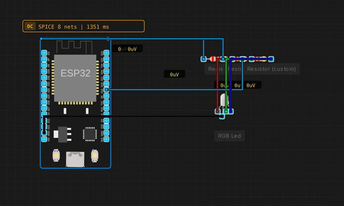
ESP32 LEDC PWM RGB
ESP32 LEDC peripheral drives RGB LED with independent PWM channels.
ESP32 OLED Smart UI Eyes Animation Time & Weather (MicroPython)
ESP32 OLED Smart UI Eyes Animation Time & Weather (MicroPython) on ESP32 (MicroPython) — uses OLED, Wi-Fi. From Kritish Mohapatra's 100 Days of IoT series: https://github.com/kritishmohapatra/100_Days_100_IoT_Projects
ESP32 Serial Echo
ESP32 reads from Serial and echoes back. Demonstrates multi-UART and Serial Monitor integration.
ESP32 WiFi + MQTT
Connect an ESP32 to WiFi and a public MQTT broker. The sketch publishes to its own topic and subscribes to it, so every message round-trips through broker.hivemq.com and toggles GPIO2 — a self-contained test of WiFi and MQTT with no external setup. Open the Serial Monitor at 115200 to watch it connect and exchange messages. The emulator advertises an open AP named "Velxio-GUEST".
ESP32 WiFi Connect
Connect to the virtual "Velxio-GUEST" WiFi network and print the assigned IP address. Uses channel 6 for faster connection.
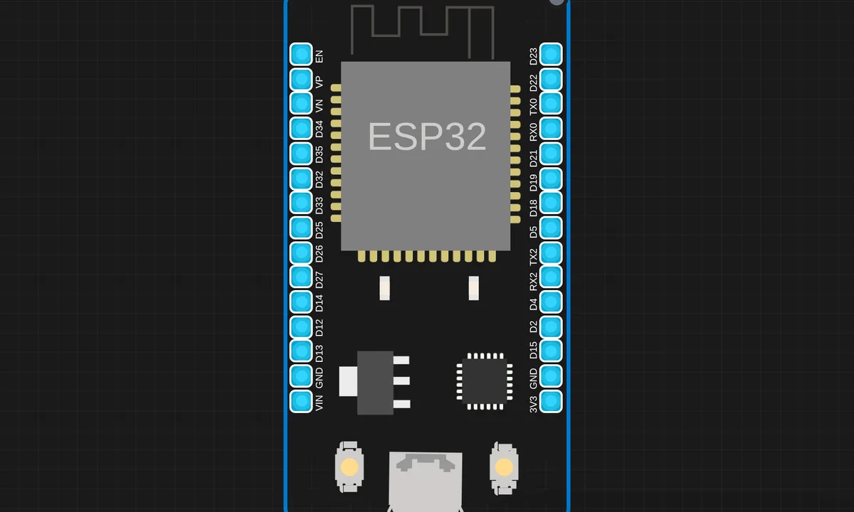
ESP32 WiFi Scan
Scan for available WiFi networks and display them in Serial Monitor. The emulated ESP32 will find the "Velxio-GUEST" access point.
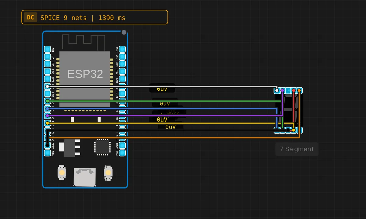
ESP32: 7-Segment Counter
Count 0–9 on a 7-segment display driven from GPIO 12, 13, 14, 25, 26, 27, 32 on the ESP32.
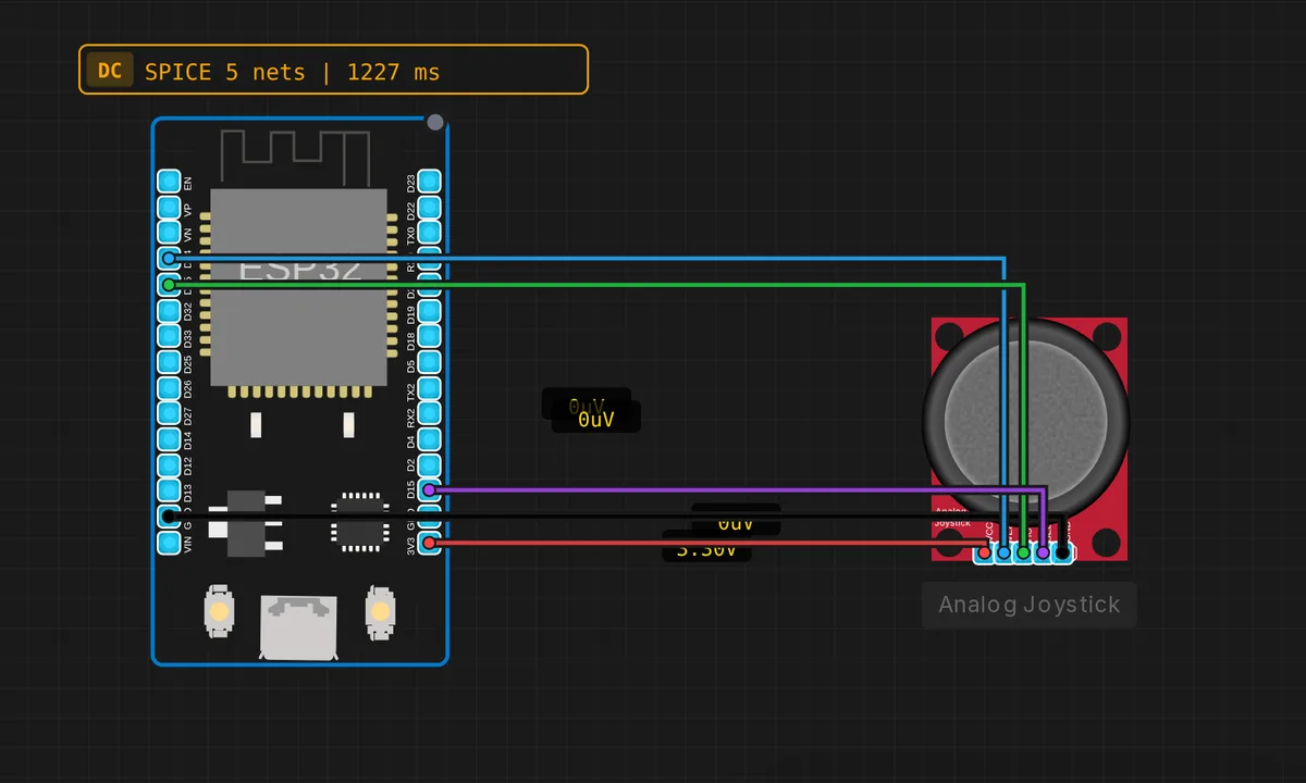
ESP32: Analog Joystick
Read X/Y axes and button click from an analog joystick on the ESP32. X on D35, Y on D34, button on GPIO15.
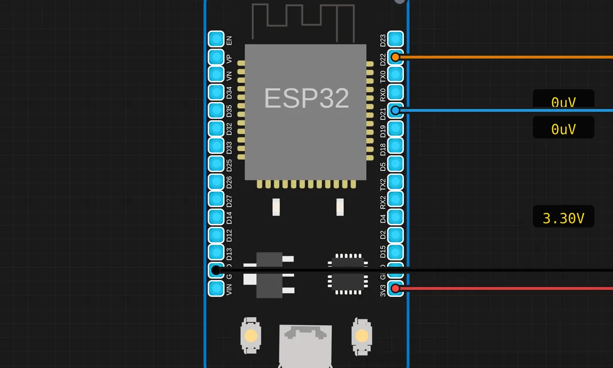
ESP32: BMP280 Weather Station
Read temperature and pressure from a BMP280 barometric sensor over I2C (SDA=D21, SCL=D22).
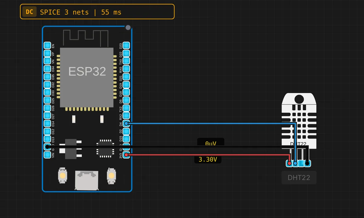
ESP32: DHT22 Temperature & Humidity
Read temperature and humidity from a DHT22 sensor on GPIO4 of the ESP32.
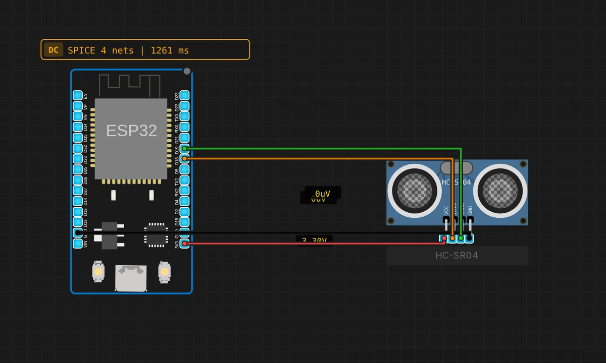
ESP32: HC-SR04 Ultrasonic Distance
Measure distance with an HC-SR04 sensor on ESP32. TRIG on GPIO18, ECHO on GPIO19.
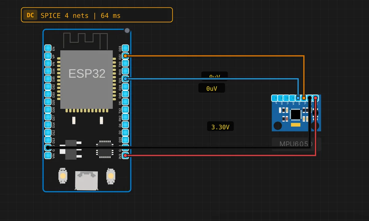
ESP32: MPU-6050 Accelerometer
Read 3-axis acceleration and gyroscope data from an MPU-6050 over I2C (SDA=D21, SCL=D22).
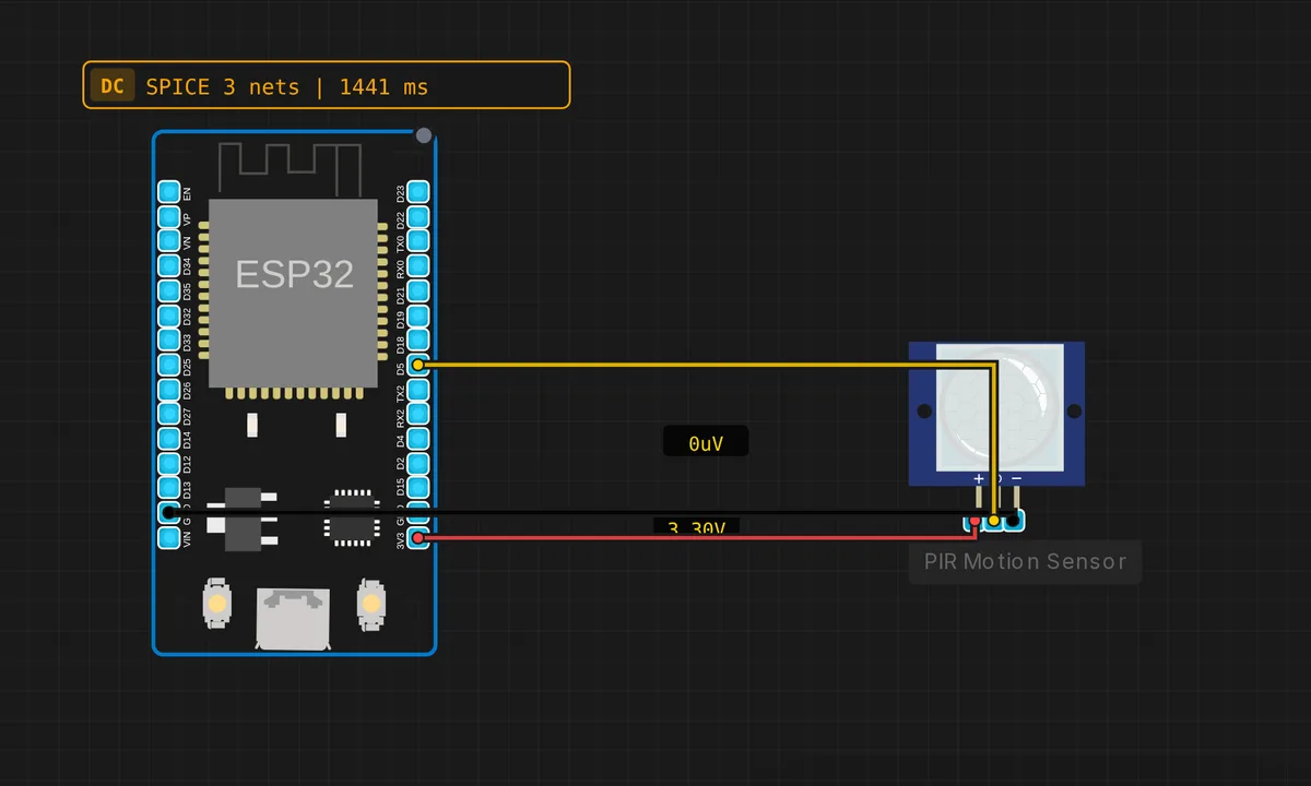
ESP32: PIR Motion Detector
Detect motion with a PIR sensor on GPIO5 of the ESP32. Logs events to Serial with timestamps.
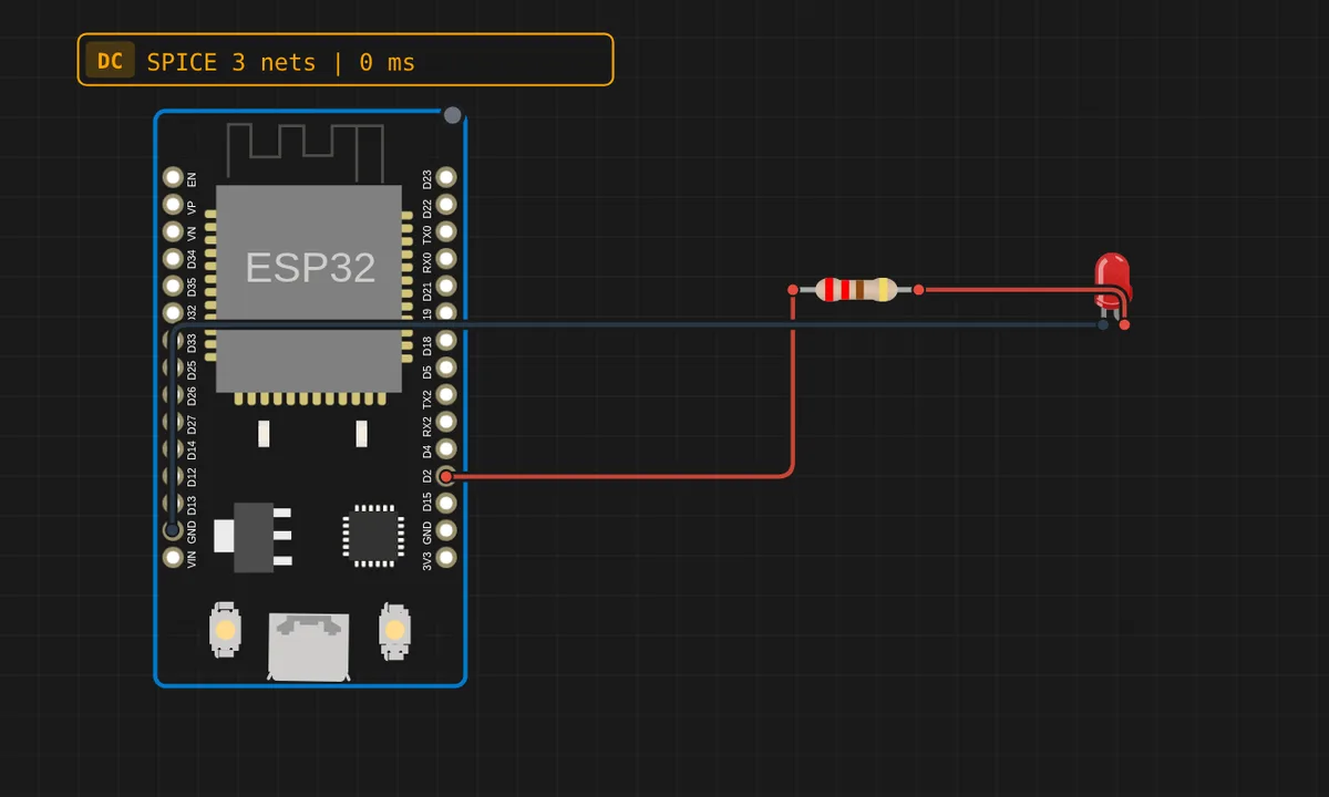
ESP32: Pure ESP-IDF Blink
Blink an LED from a pure ESP-IDF project — app_main(), FreeRTOS delays and the GPIO driver, no Arduino core. Pick "ESP-IDF" in the language selector to write more projects like this.
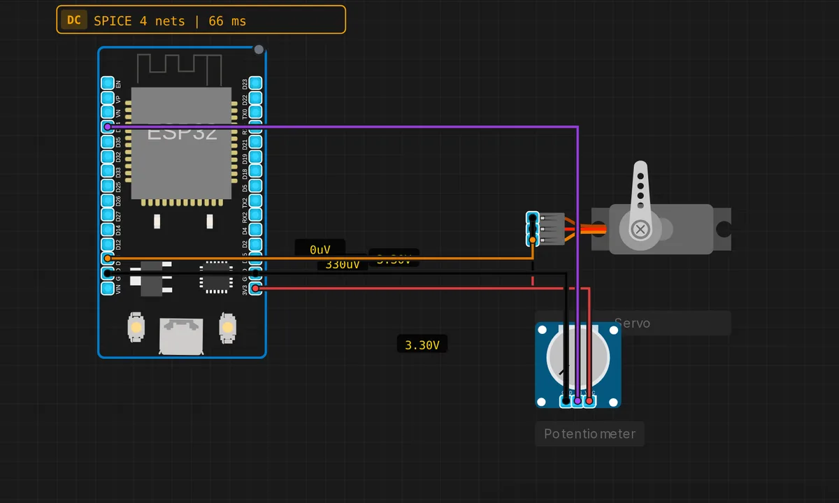
ESP32: Servo Motor + Potentiometer
Control a servo motor angle directly with a potentiometer. The servo follows the pot position in real time.
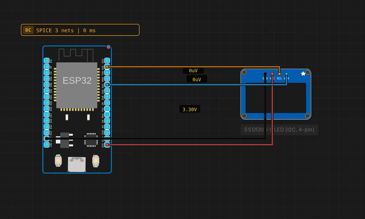
ESP32: SSD1306 OLED (4-pin I2C)
Drive the cheap 4-pin SSD1306 OLED module (GND/VCC/SCL/SDA) over I2C from an ESP32 (SDA=21, SCL=22).
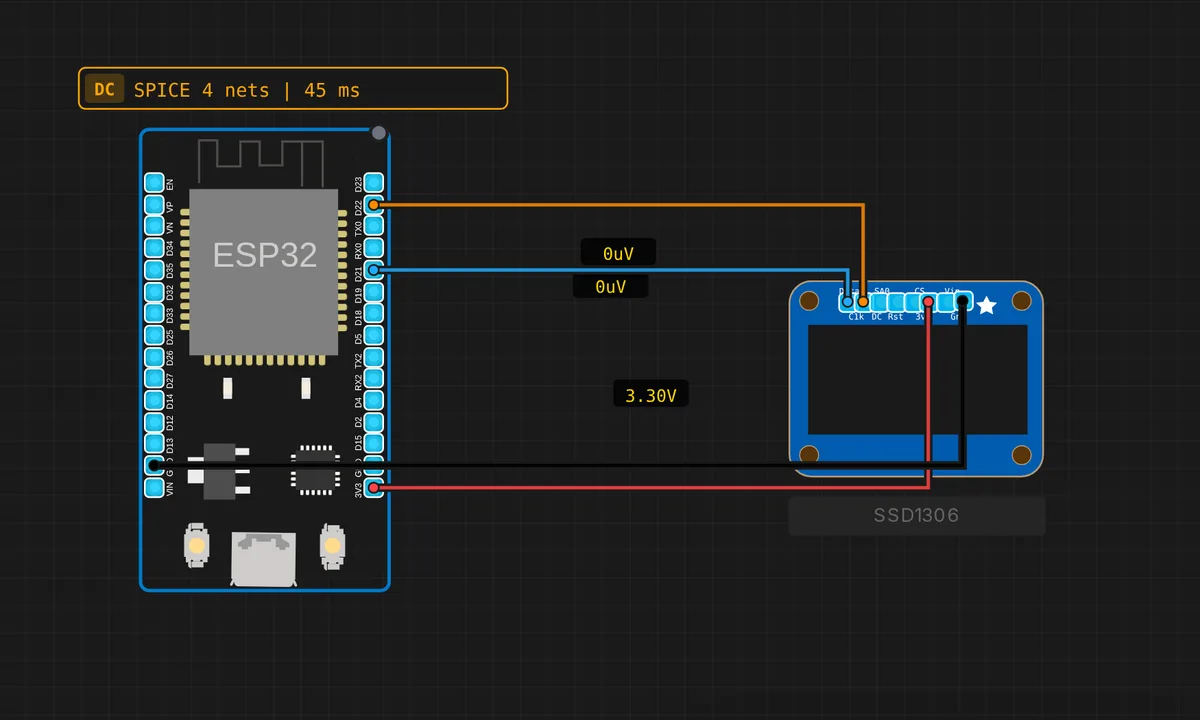
ESP32: SSD1306 OLED Display
Display text and graphics on a 128×64 SSD1306 OLED over I2C (SDA=D21, SCL=D22).
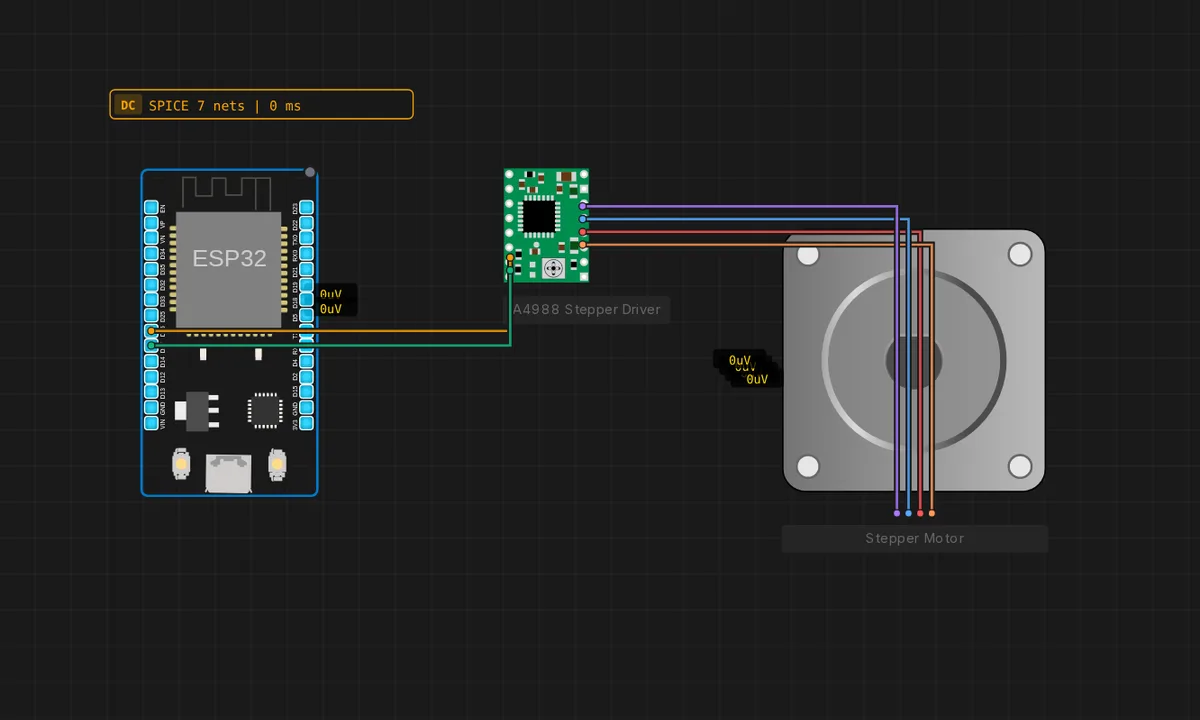
ESP32: Stepper + A4988
Spin a bipolar stepper motor from an ESP32 through an A4988 driver (STEP = GPIO26, DIR = GPIO27).
Flask Server Based LED Control using MicroPython
Flask Server Based LED Control using MicroPython on ESP32 (MicroPython) — uses HTTP server, Wi-Fi. From Kritish Mohapatra's 100 Days of IoT series: https://github.com/kritishmohapatra/100_Days_100_IoT_Projects
IoT Atmospheric Monitoring System using ESP32, wowki & Blynk
IoT Atmospheric Monitoring System using ESP32, wowki & Blynk on ESP32 (MicroPython) — uses Blynk, Blynk Cloud, Wi-Fi. From Kritish Mohapatra's 100 Days of IoT series: https://github.com/kritishmohapatra/100_Days_100_IoT_Projects
IoT Based DSM Smart Metering
IoT Based DSM Smart Metering on ESP32 (MicroPython) — uses Blynk, Blynk Cloud, OTA, Wi-Fi. From Kritish Mohapatra's 100 Days of IoT series: https://github.com/kritishmohapatra/100_Days_100_IoT_Projects
IoT Environment Monitoring With Anomaly Detection
IoT Environment Monitoring With Anomaly Detection on ESP32 (MicroPython) — uses DHT, LDR, ThingSpeak, Wi-Fi. From Kritish Mohapatra's 100 Days of IoT series: https://github.com/kritishmohapatra/100_Days_100_IoT_Projects
IoT Smart Irrigation System
IoT Smart Irrigation System on ESP32 (MicroPython) — uses Blynk, Blynk Cloud, Wi-Fi. From Kritish Mohapatra's 100 Days of IoT series: https://github.com/kritishmohapatra/100_Days_100_IoT_Projects
Joystick Controlled Servo
Joystick Controlled Servo on ESP32 (MicroPython) — uses Servo. From Kritish Mohapatra's 100 Days of IoT series: https://github.com/kritishmohapatra/100_Days_100_IoT_Projects
MicroPython Watch
MicroPython Watch on ESP32 (MicroPython) — uses OLED, Wi-Fi. From Kritish Mohapatra's 100 Days of IoT series: https://github.com/kritishmohapatra/100_Days_100_IoT_Projects
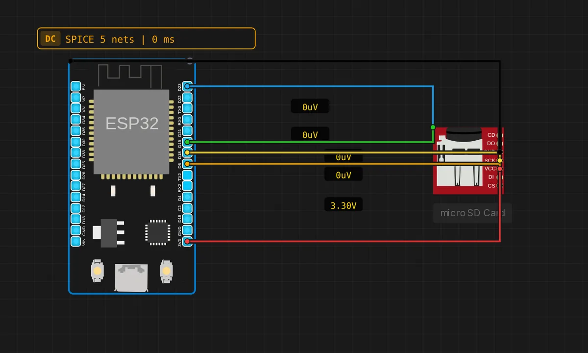
microSD Card (ESP32)
Read and write files on a microSD card over SPI on the ESP32 (VSPI). The card is pre-loaded with this project's own files (free auto-copy); paid users can upload their own files from the component's "SD Card" panel. Lists the root directory, then writes /log.txt and reads it back. Open the Serial Monitor at 115200 baud.
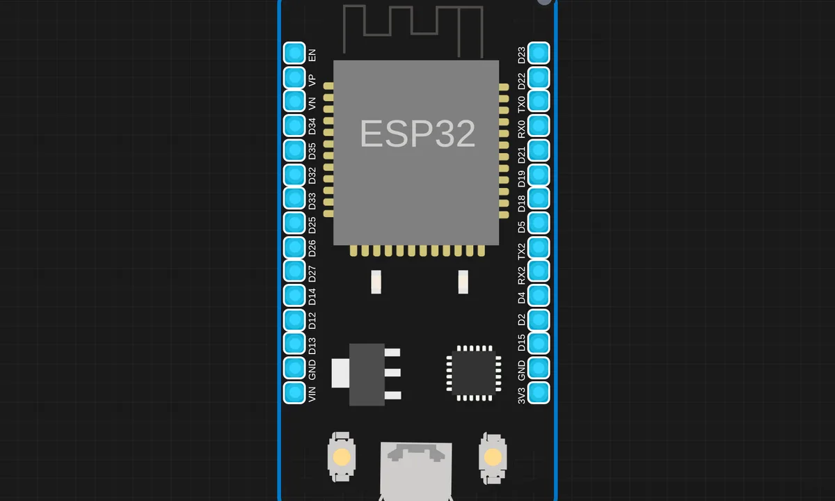
MQ 135 Gas Sensor with ESP32 (MicroPython)
MQ 135 Gas Sensor with ESP32 (MicroPython) on ESP32 (MicroPython) — uses OTA. From Kritish Mohapatra's 100 Days of IoT series: https://github.com/kritishmohapatra/100_Days_100_IoT_Projects
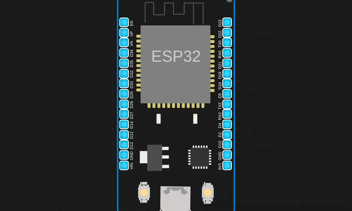
MQ4 Gas Leak Detection System using ESP32 and MicroPython
MQ4 Gas Leak Detection System using ESP32 and MicroPython on ESP32 (MicroPython). From Kritish Mohapatra's 100 Days of IoT series: https://github.com/kritishmohapatra/100_Days_100_IoT_Projects
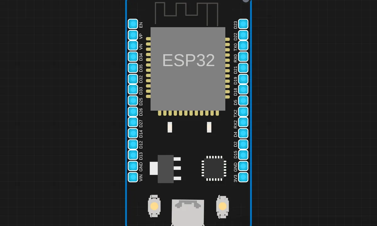
MQ7 CO Gas Detection ESP32
MQ7 CO Gas Detection ESP32 on ESP32 (MicroPython). From Kritish Mohapatra's 100 Days of IoT series: https://github.com/kritishmohapatra/100_Days_100_IoT_Projects
NTP Synchronized Digital Clock using ESP32 & MAX7219
NTP Synchronized Digital Clock using ESP32 & MAX7219 on ESP32 (MicroPython) — uses MAX7219, Wi-Fi. From Kritish Mohapatra's 100 Days of IoT series: https://github.com/kritishmohapatra/100_Days_100_IoT_Projects
Password Lock System using ESP32
Password Lock System using ESP32 on ESP32 (MicroPython) — uses I²C LCD. From Kritish Mohapatra's 100 Days of IoT series: https://github.com/kritishmohapatra/100_Days_100_IoT_Projects
Potentiometer Visualizer
Potentiometer Visualizer on ESP32 (MicroPython). From Kritish Mohapatra's 100 Days of IoT series: https://github.com/kritishmohapatra/100_Days_100_IoT_Projects
Pulse Monitor
Pulse Monitor on ESP32 (MicroPython) — uses OLED. From Kritish Mohapatra's 100 Days of IoT series: https://github.com/kritishmohapatra/100_Days_100_IoT_Projects
RGB Color Mixer using Potentiometers (ESP32 + MicroPython)
RGB Color Mixer using Potentiometers (ESP32 + MicroPython) on ESP32 (MicroPython) — uses Servo. From Kritish Mohapatra's 100 Days of IoT series: https://github.com/kritishmohapatra/100_Days_100_IoT_Projects
Smart Home Automation System
Smart Home Automation System on ESP32 (MicroPython) — uses Blynk, Blynk Cloud, DHT, Wi-Fi. From Kritish Mohapatra's 100 Days of IoT series: https://github.com/kritishmohapatra/100_Days_100_IoT_Projects
Smart Indoor Security System
Smart Indoor Security System on ESP32 (MicroPython) — uses Wi-Fi. From Kritish Mohapatra's 100 Days of IoT series: https://github.com/kritishmohapatra/100_Days_100_IoT_Projects
Smart IoT Gas Monitoring System
Smart IoT Gas Monitoring System on ESP32 (MicroPython) — uses DHT, HTTP server, Wi-Fi. From Kritish Mohapatra's 100 Days of IoT series: https://github.com/kritishmohapatra/100_Days_100_IoT_Projects
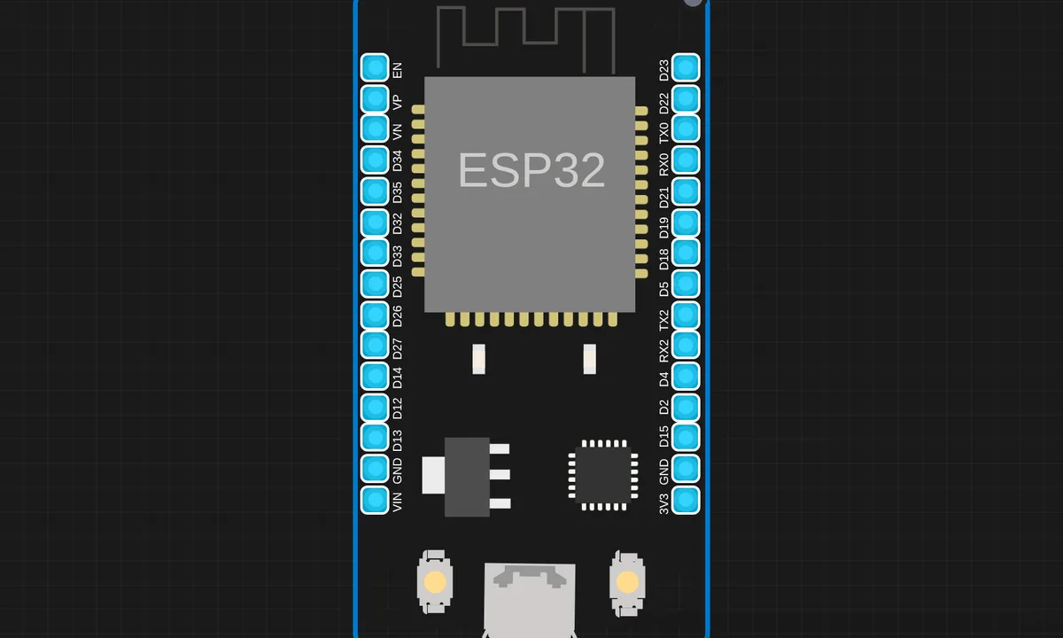
Stepper Motor Control using ESP32 & A4988 (MicroPython)
Stepper Motor Control using ESP32 & A4988 (MicroPython) on ESP32 (MicroPython) — uses Stepper. From Kritish Mohapatra's 100 Days of IoT series: https://github.com/kritishmohapatra/100_Days_100_IoT_Projects
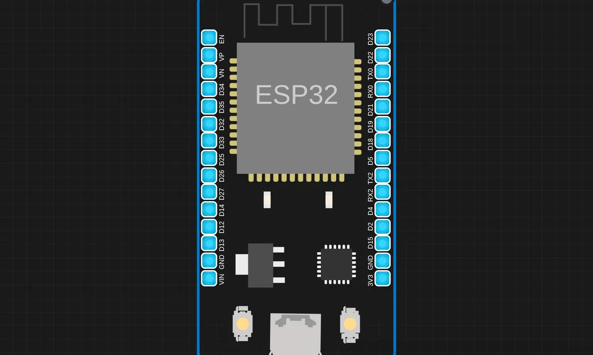
Temperature Based LED Indicator (MicroPython ESP32)
Temperature Based LED Indicator (MicroPython ESP32) on ESP32 (MicroPython) — uses DHT. From Kritish Mohapatra's 100 Days of IoT series: https://github.com/kritishmohapatra/100_Days_100_IoT_Projects
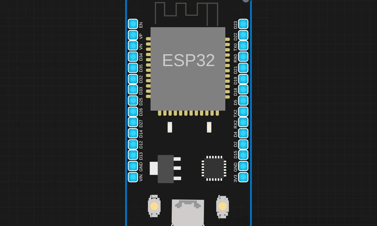
Ultrasonic LED Distance Indicator ESP32 MicroPython
Ultrasonic LED Distance Indicator ESP32 MicroPython on ESP32 (MicroPython) — uses HC-SR04. From Kritish Mohapatra's 100 Days of IoT series: https://github.com/kritishmohapatra/100_Days_100_IoT_Projects
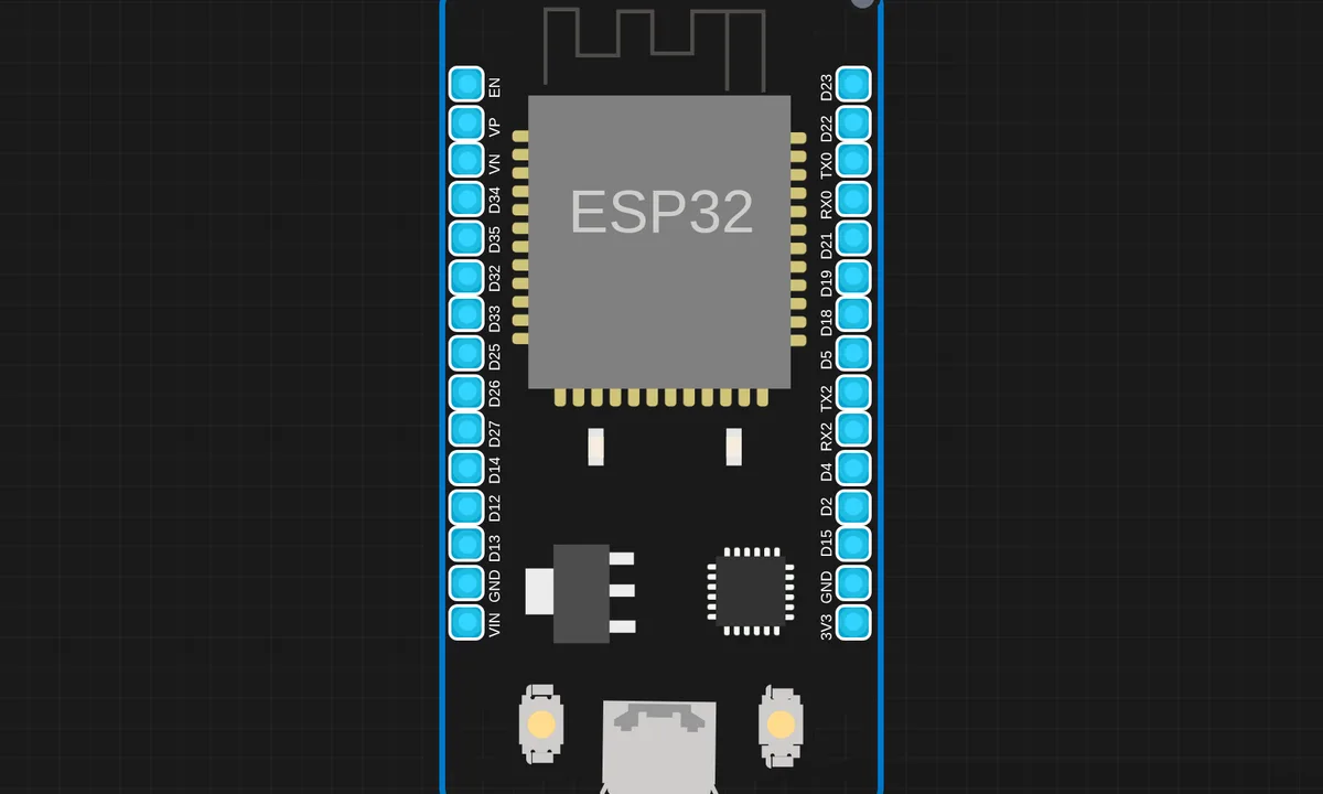
Wi Fi Controlled 4WD Robot Car
Wi Fi Controlled 4WD Robot Car on ESP32 (MicroPython) — uses Wi-Fi. From Kritish Mohapatra's 100 Days of IoT series: https://github.com/kritishmohapatra/100_Days_100_IoT_Projects
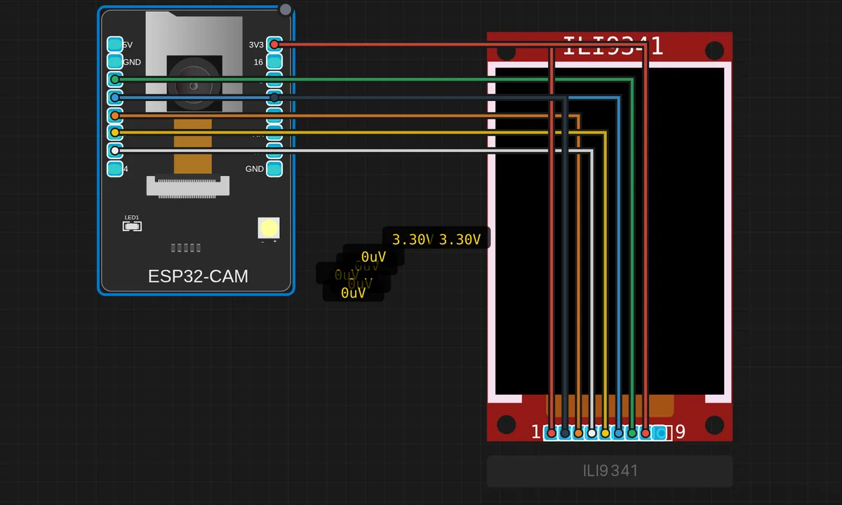
ESP32-CAM + ILI9341 Live Preview
Webcam frames decoded in-place with jpg2rgb565() and rendered to a 320×240 SPI TFT (160×120 centered, 1/2 scale). Status bar shows fps, frame counter, decode-fail counter and a live pulse. Requires Adafruit GFX + Adafruit ILI9341 libraries.
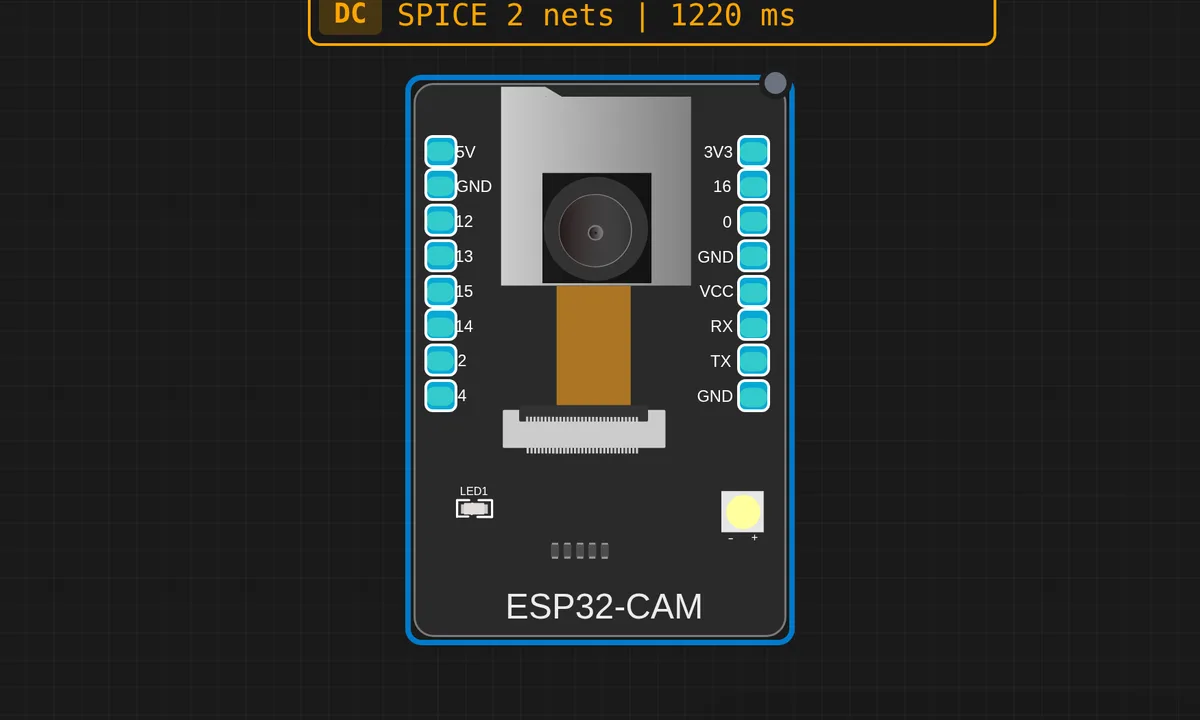
ESP32-CAM: Webcam Demo
Init the OV2640 camera, verify chip-id over SCCB, then loop on esp_camera_fb_get() and print frame metadata to Serial. The simplest "is the emulation alive" sketch — click Camera in the canvas header to start streaming your webcam.
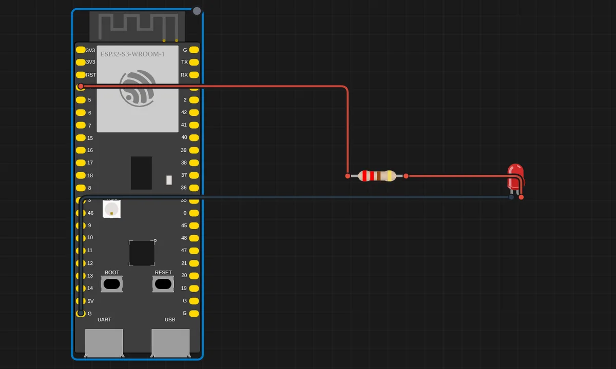
ESP32-S3 Blink LED
Blink an external red LED on GPIO4 of the ESP32-S3 DevKitC-1. Verifies ESP32-S3 GPIO emulation is working.
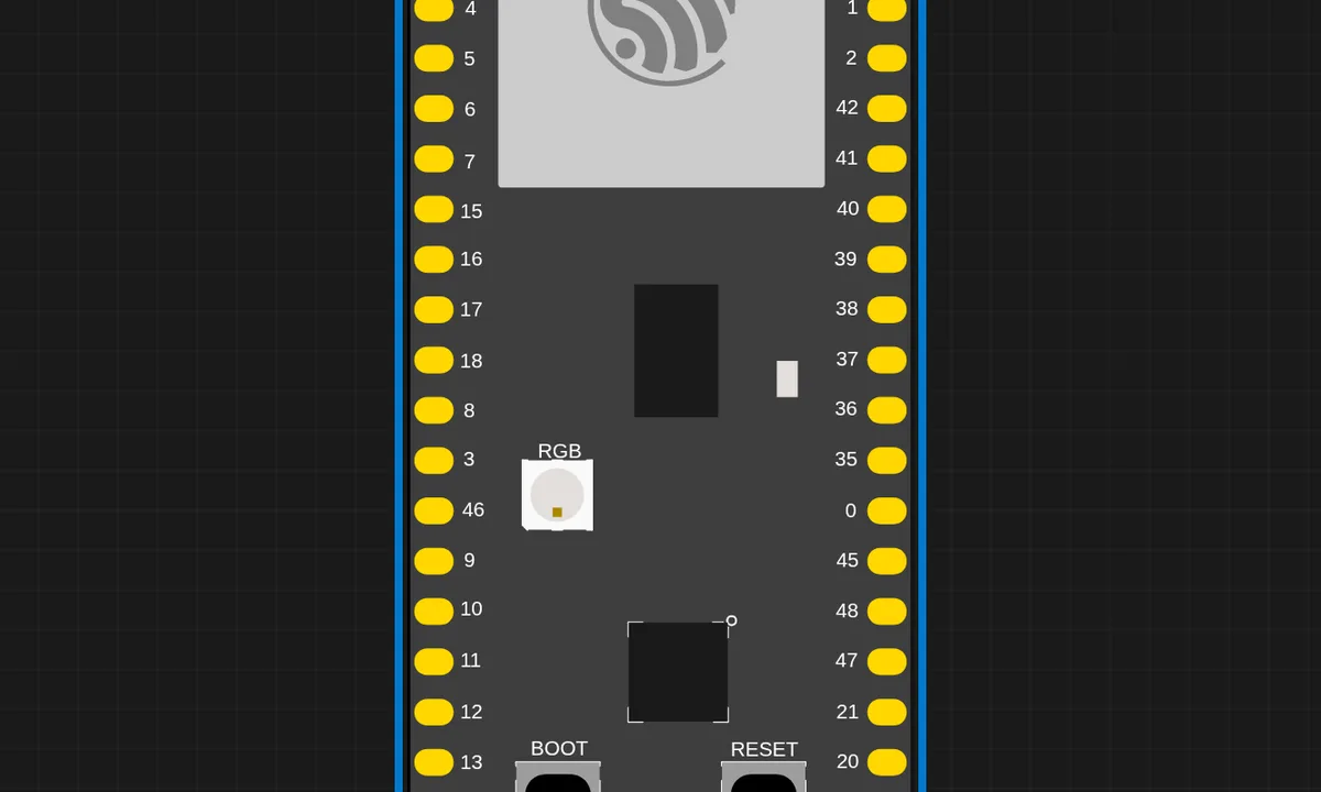
ESP32-S3 Serial Echo
ESP32-S3 reads from Serial and echoes back. Demonstrates UART and Serial Monitor integration on the S3.
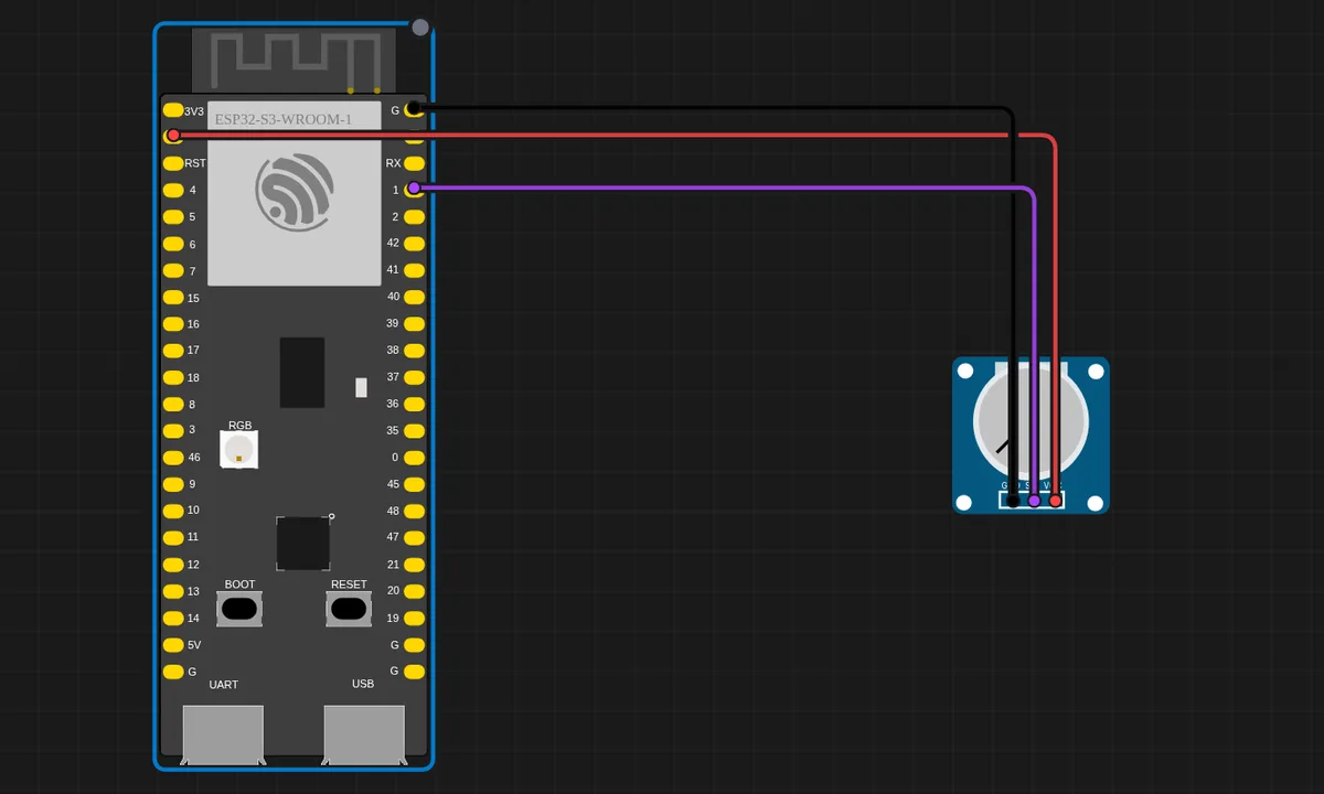
ESP32-S3: Potentiometer (ADC)
Read a potentiometer with the ESP32-S3 12-bit ADC on GPIO1 (ADC1_CH0) and print the raw value and voltage.
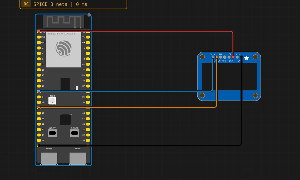
ESP32-S3: SSD1306 OLED Display
Display text on a 128×64 SSD1306 OLED over I2C from the ESP32-S3 (default Wire pins SDA=GPIO8, SCL=GPIO9).
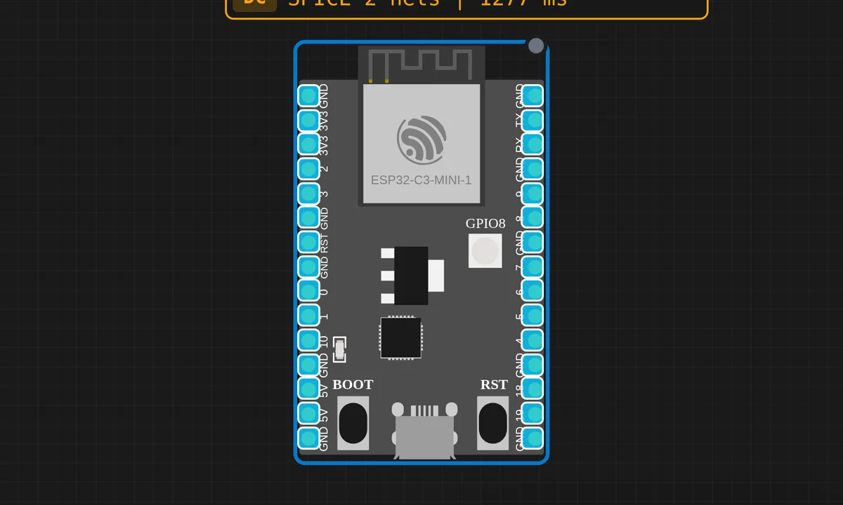
ESP32-C3 BLE Advertise
Initialize BLE 5.0 and start advertising on the ESP32-C3. Note: The ESP32-C3 only supports BLE (no Classic Bluetooth). BLE initialization is detected but actual communication is not emulated.
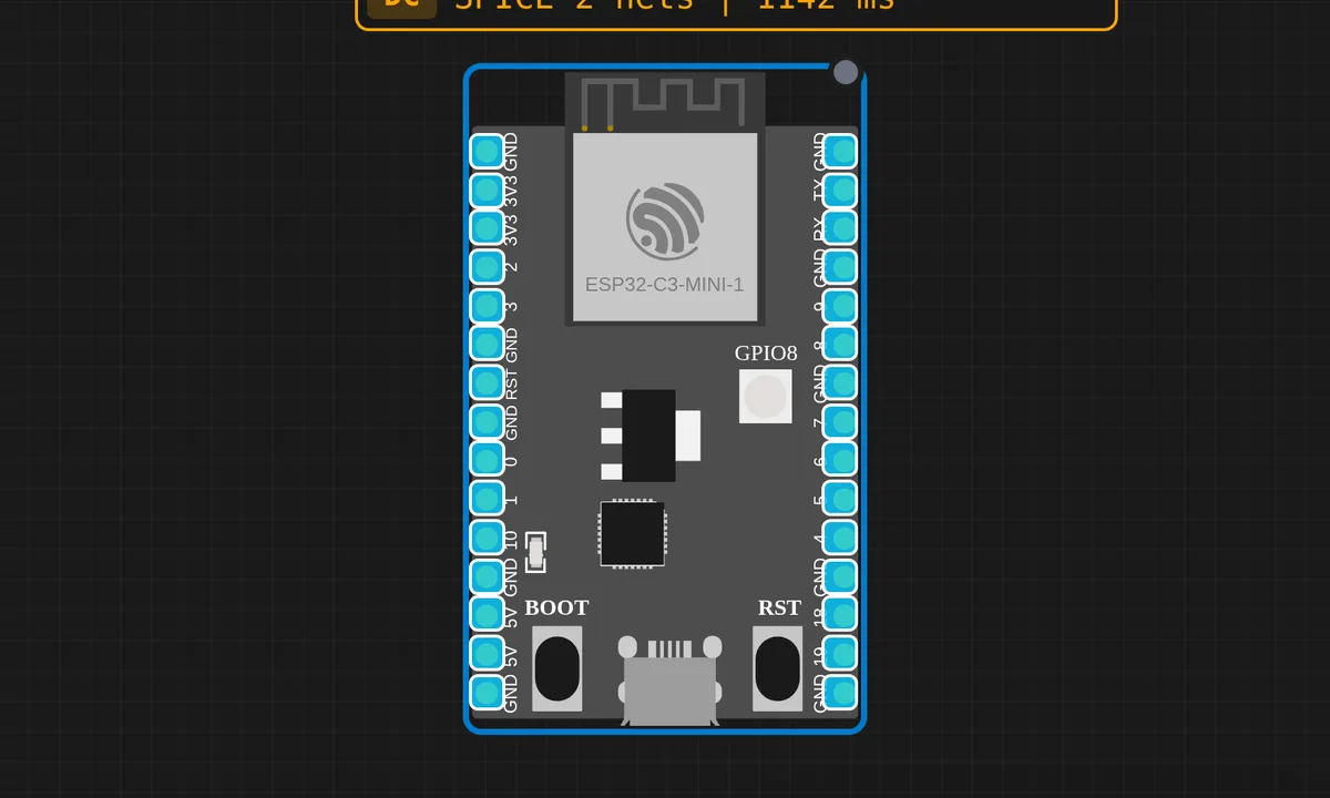
ESP32-C3 HTTP Server
Run a simple web server on the ESP32-C3. After connecting to WiFi, the server responds with an HTML page. Access it via the IoT Gateway link.
ESP32-C3 WiFi Connect
Connect the ESP32-C3 to the virtual "Velxio-GUEST" WiFi network and print the assigned IP address. Uses channel 6 for faster connection.
ESP32-C3 WiFi Scan
Scan for available WiFi networks on the ESP32-C3 (RISC-V). The emulated ESP32-C3 will find the "Velxio-GUEST" access point.
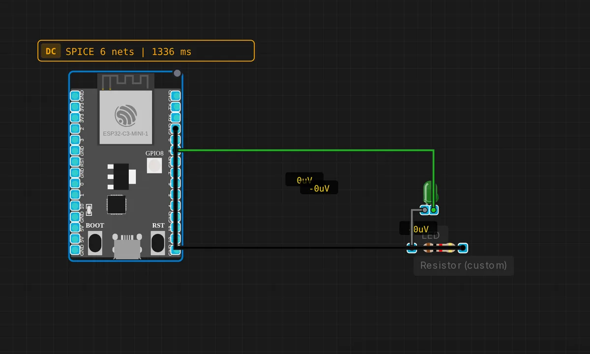
ESP32-C3: Blink LED
Blink an LED on GPIO 8 of the ESP32-C3. Runs through the QEMU lcgamboa backend (libqemu-riscv32) at 160 MHz.
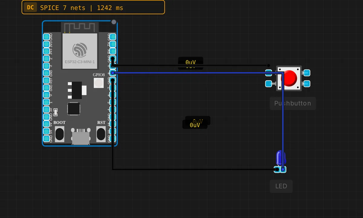
ESP32-C3: Button + LED
Press a button on GPIO 9 to toggle an LED on GPIO 8. Tests GPIO input on the browser ESP32-C3 emulator.
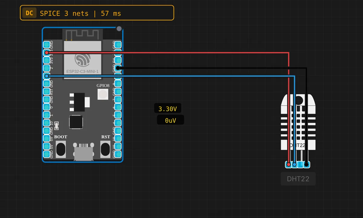
ESP32-C3: DHT22 Temperature & Humidity
Read temperature and humidity with a DHT22 sensor on GPIO3 of the ESP32-C3 RISC-V board.
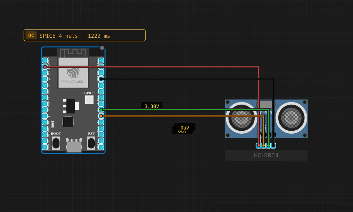
ESP32-C3: HC-SR04 Ultrasonic Distance
Measure distance with an HC-SR04 sensor on the ESP32-C3. TRIG on GPIO5, ECHO on GPIO6.
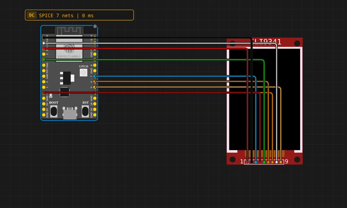
ESP32-C3: ILI9341 TFT Display (SPI)
Draws a filled screen, a rounded rectangle and text on a 320x240 ILI9341 TFT from an ESP32-C3 over hardware SPI (FSPI: SCK=4, MISO=5, MOSI=6, CS=7).
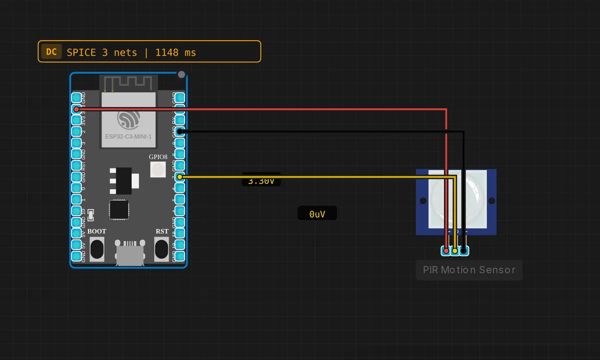
ESP32-C3: PIR Motion Detector
Detect motion with a PIR sensor on GPIO7 of the ESP32-C3. Prints detection events and count to Serial.
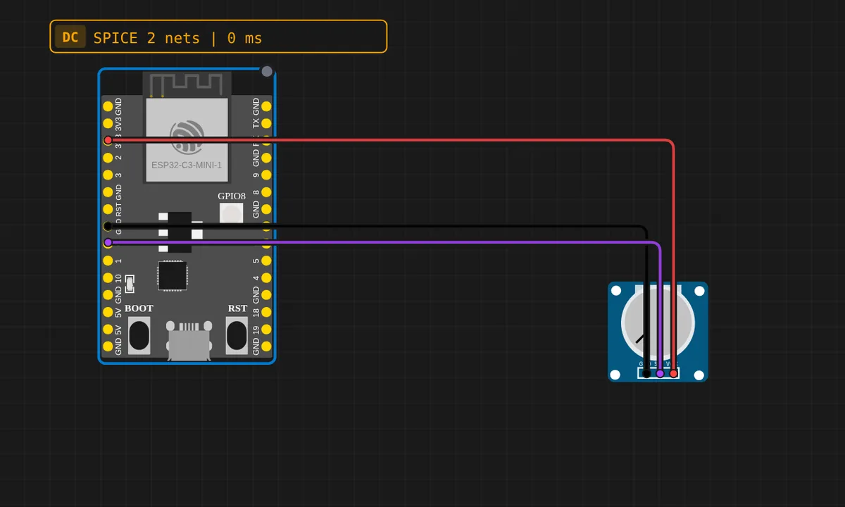
ESP32-C3: Potentiometer (ADC)
Read a potentiometer with the ESP32-C3 12-bit ADC on GPIO0 (ADC1_CH0) and print the raw value and voltage.
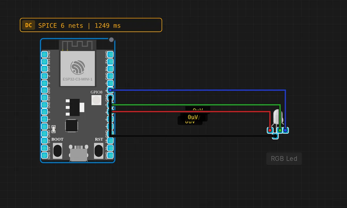
ESP32-C3: RGB LED
Cycle through red, green, and blue on an RGB LED using GPIO 6, 7, 8 on the ESP32-C3.
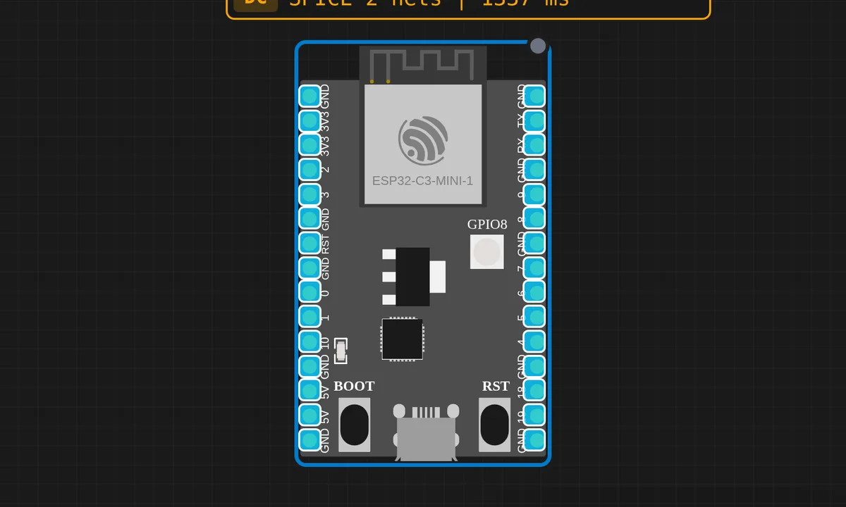
ESP32-C3: Serial Echo
Type in Serial Monitor and see it echoed back by the ESP32-C3 browser emulator.
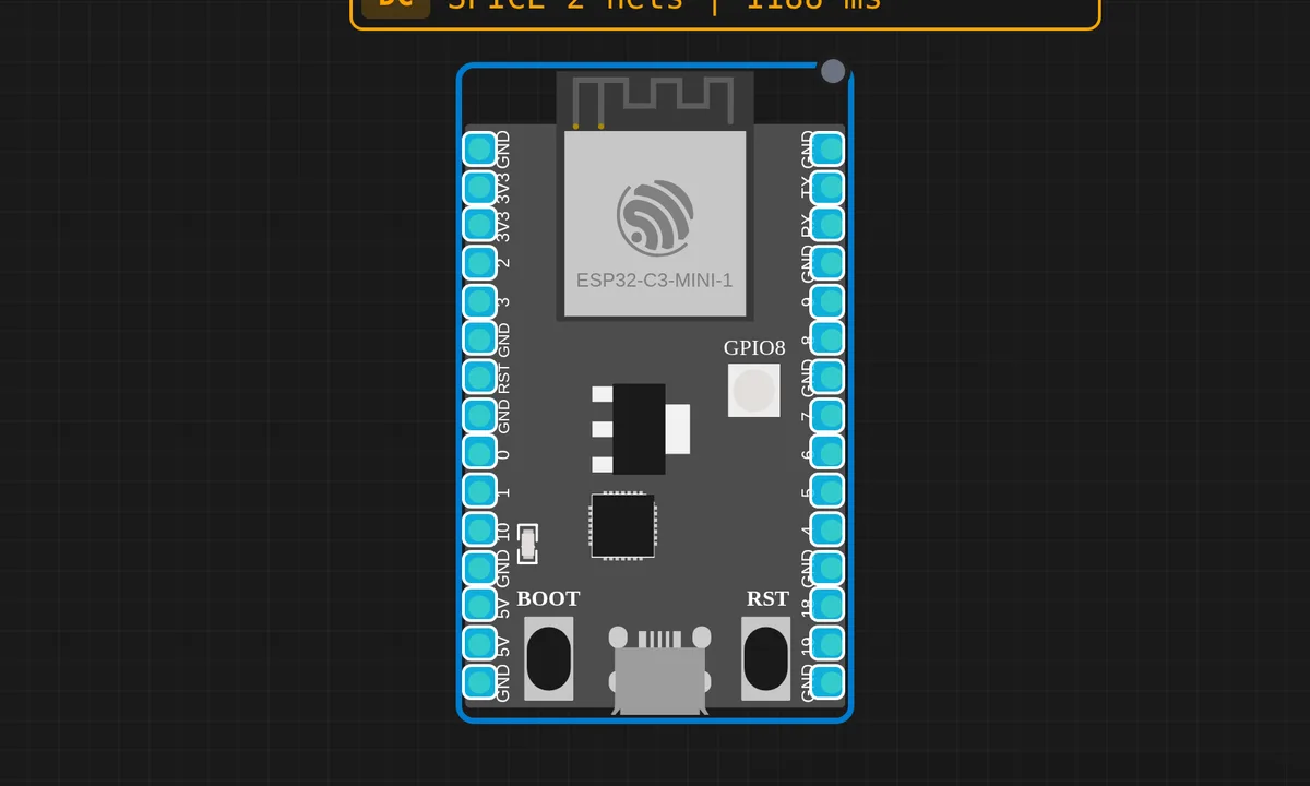
ESP32-C3: Serial Hello
Print Hello World and a heartbeat every second from ESP32-C3 via Serial. Runs in the browser.
ESP32-C3: Servo Motor Sweep
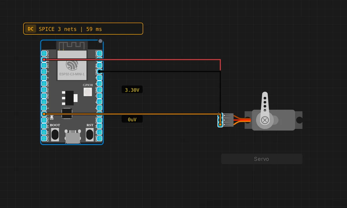
Sweep a servo motor from 0° to 180° and back on the ESP32-C3 using GPIO10 (PWM).
ESP32-C3: SSD1306 OLED Display
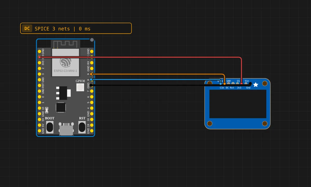
Display text on a 128×64 SSD1306 OLED over I2C from the ESP32-C3 (default Wire pins SDA=GPIO8, SCL=GPIO9).
![[STM32 + Arduino] GPIO Mirror](/examples-thumbs/stm32-uno-gpio-mirror.webp)
[STM32 + Arduino] GPIO Mirror
Cross-board demo: the STM32 Blue Pill toggles PA1 every 500 ms (wired to Arduino Uno pin 2). The Uno reads pin 2 and mirrors it to its built-in LED (pin 13). Shows heterogeneous multi-board simulation — QEMU STM32 driving an avr8js Arduino.
![[STM32 + Arduino] Serial Link](/examples-thumbs/stm32-uno-serial-link.webp)
[STM32 + Arduino] Serial Link
Cross-board UART: the STM32 Blue Pill sends a "PING n" message over USART1 (PA9 TX) into the Arduino Uno RX (pin 0). The Uno reads each line and blinks LED 13 + echoes "[Uno] got: ..." to its own Serial Monitor. Watch both monitors.
![[STM32 + ESP32] GPIO Sync](/examples-thumbs/stm32-esp32-gpio-sync.webp)
[STM32 + ESP32] GPIO Sync
Cross-board demo: the STM32 Blue Pill toggles PA1 (wired to ESP32 GPIO4). The ESP32 reads GPIO4 and prints its state + mirrors it onto GPIO2. Two QEMU backends (libqemu-arm + libqemu-xtensa) talking over a wire.
![[STM32 + STM32] Blue Pill → Black Pill](/examples-thumbs/stm32-bluepill-blackpill-gpio.webp)
[STM32 + STM32] Blue Pill → Black Pill
Two different STM32 boards talking: the Blue Pill (F103) toggles PA1, wired to the Black Pill (F411) PA0. The Black Pill reads PA0 and mirrors it to its onboard PC13 LED. Both run on separate libqemu-arm QEMU instances.
STM32 Blue Pill Blink
Blink the onboard PC13 LED and print to Serial on an STM32F103 Blue Pill (QEMU / libqemu-arm)
STM32 Blue Pill: SSD1306 OLED (4-pin I2C)
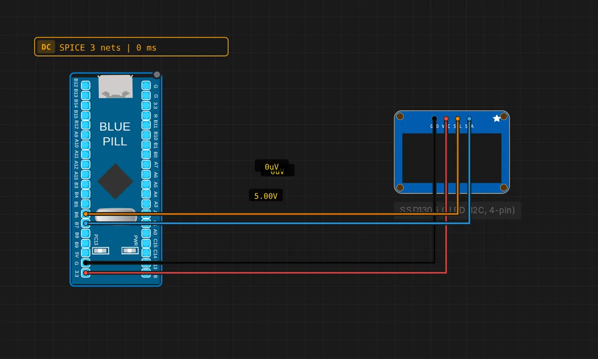
Drive the cheap 4-pin SSD1306 OLED module (GND/VCC/SCL/SDA) over I2C1 from an STM32 Blue Pill (SDA=PB7, SCL=PB6).
STM32 Serial Counter
STM32 Blue Pill prints an incrementing counter and uptime to Serial every second. Open the Serial Monitor to watch it. Onboard PC13 LED blinks as a heartbeat.
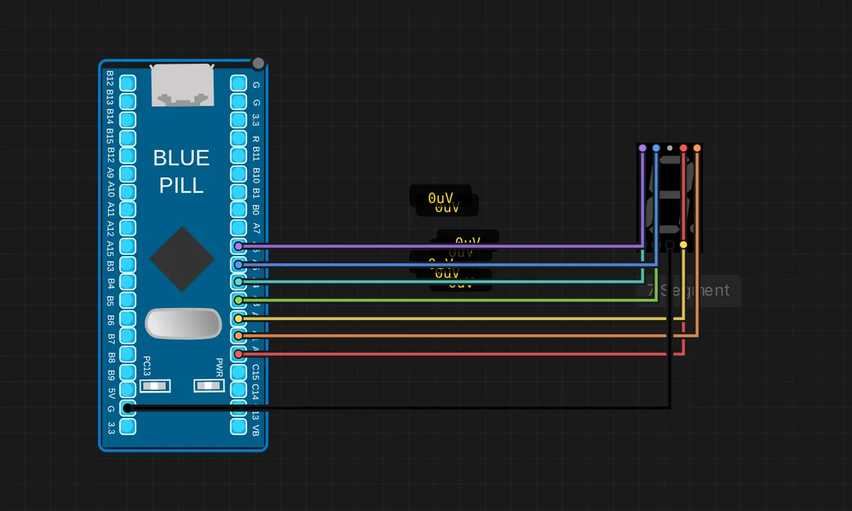
STM32: 7-Segment Counter
Count 0-9 on a 7-segment display driven by seven GPIO pins (PA0-PA6 = segments A-G) on the STM32 Blue Pill. Pure digital output: each digit pattern is written to the segment pins. Common-cathode (COM -> GND).
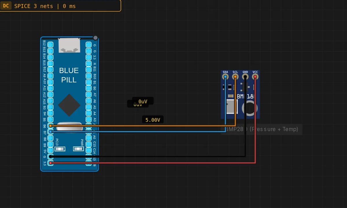
STM32: BMP280 Weather Sensor (I2C)
Read temperature and pressure from a BMP280 over I2C1 on an STM32 Blue Pill (SCL=PB6, SDA=PB7). The sensor runs as a QEMU I2C slave; values stream to the Serial Monitor. Demonstrates the STM32 hardware I2C master peripheral end to end.
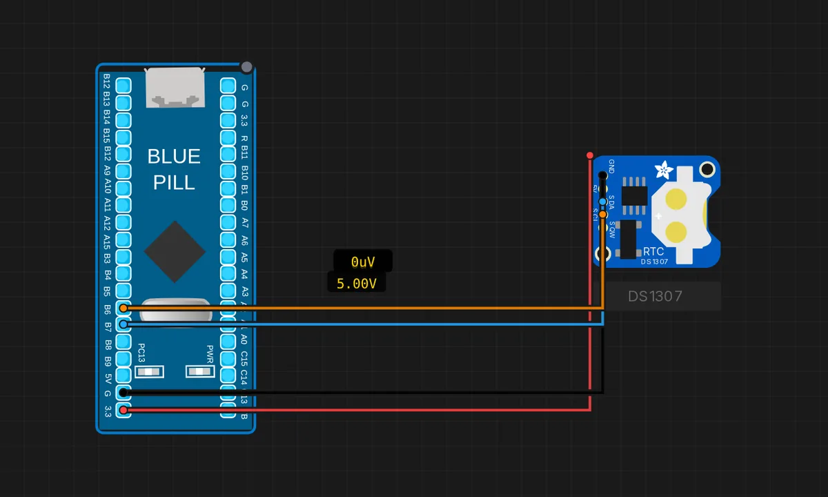
STM32: DS1307 RTC Clock (I2C)
Read the current time and date from a DS1307 real-time clock over I2C1 on the STM32 Blue Pill (SCL=PB6, SDA=PB7). The QEMU DS1307 slave returns the live system clock in BCD, ticking once a second in the Serial Monitor.
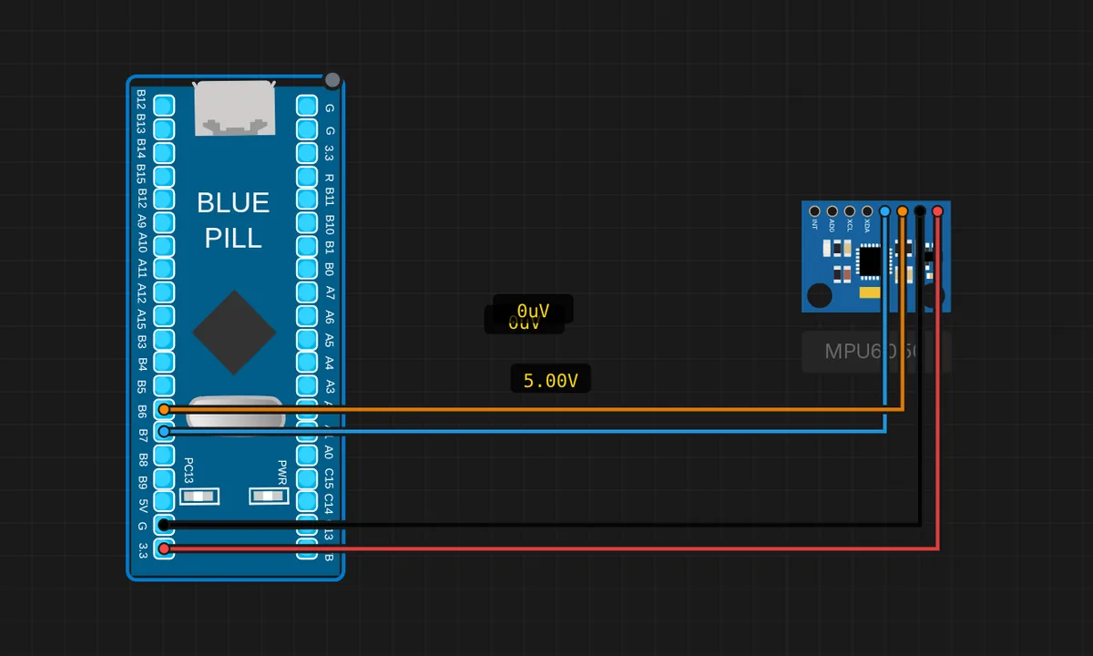
STM32: MPU6050 IMU (I2C)
Read the WHO_AM_I id and accelerometer axes from an MPU6050 6-axis IMU over I2C1 on the STM32 Blue Pill (SCL=PB6, SDA=PB7). The sensor runs as a QEMU I2C slave; raw Wire reads stream to the Serial Monitor.
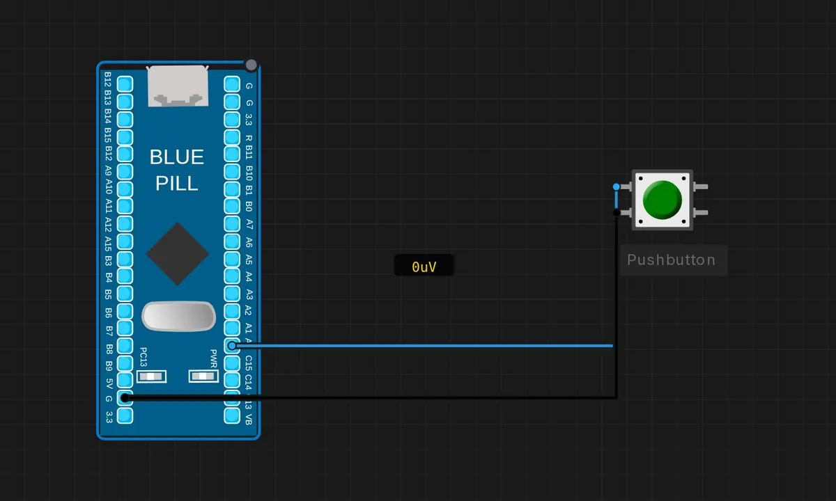
STM32: Push Button -> LED
Read a push button on PA0 (INPUT_PULLUP) and mirror it to the onboard PC13 LED on the STM32 Blue Pill. Pressing the button drives the GPIO input LOW; the firmware lights the LED while pressed. Demonstrates GPIO input injection.
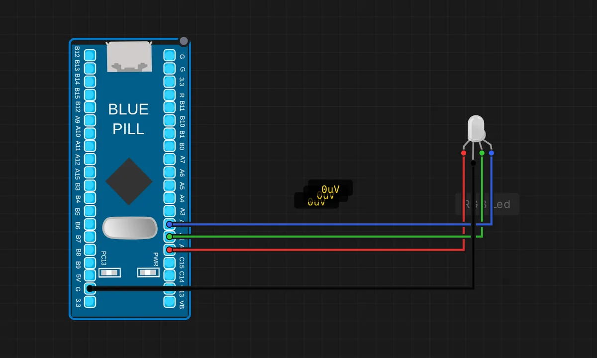
STM32: RGB LED Color Cycle
Cycle an RGB LED through red, green and blue using three GPIO pins (PA0=R, PA1=G, PA2=B) on the STM32 Blue Pill. Pure digital output; common-cathode (COM -> GND).
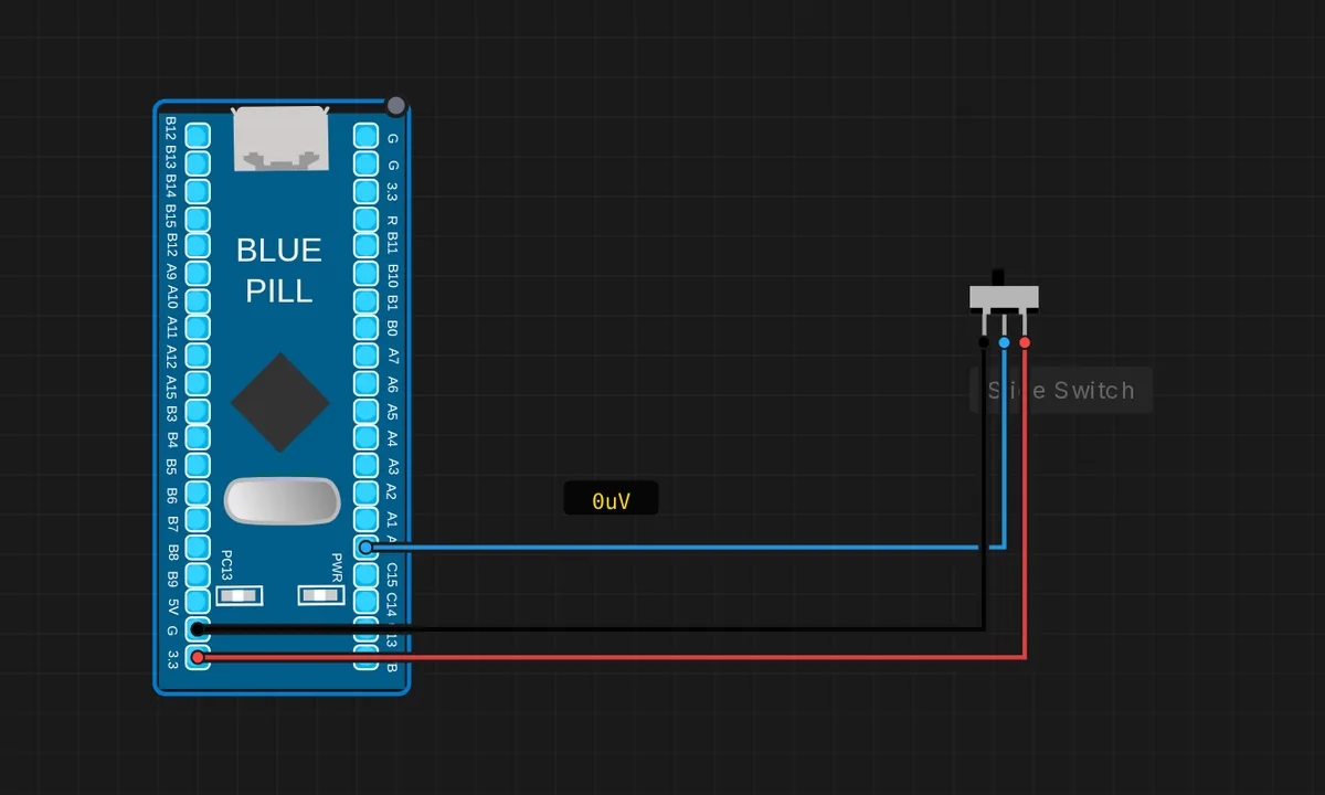
STM32: Slide Switch -> LED
Read a slide switch on PA0 and reflect its position on the onboard PC13 LED of the STM32 Blue Pill. Flipping the switch drives the GPIO input HIGH/LOW. Demonstrates GPIO input injection from a latching element.
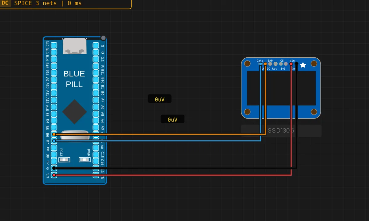
STM32: SSD1306 OLED Display (I2C)
Drive a 128x64 SSD1306 OLED over I2C1 from an STM32 Blue Pill (SCL=PB6, SDA=PB7). The framebuffer writes are captured by the QEMU I2C slave and rendered on the canvas. Shows "Hello Velxio!" with a live frame counter.
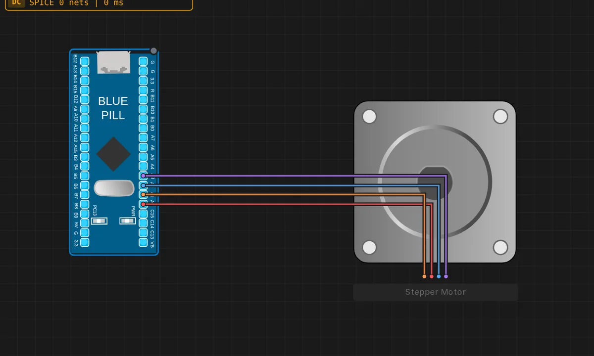
STM32: Stepper Motor
Rotate a stepper motor with the four-pin full-step sequence driven by GPIO pins (PA0-PA3) on the STM32 Blue Pill. Pure digital output: the firmware energizes coils A+, B+, A-, B- in order to step the rotor.
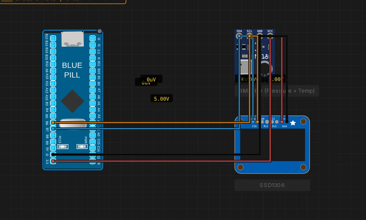
STM32: Weather Station (BMP280 + OLED)
A complete I2C dashboard on the STM32 Blue Pill: read temperature and pressure from a BMP280 and render them live on an SSD1306 OLED, both sharing the same I2C1 bus (BMP280 0x76, OLED 0x3C, SCL=PB6/SDA=PB7). Exercises I2C read and write on one bus.
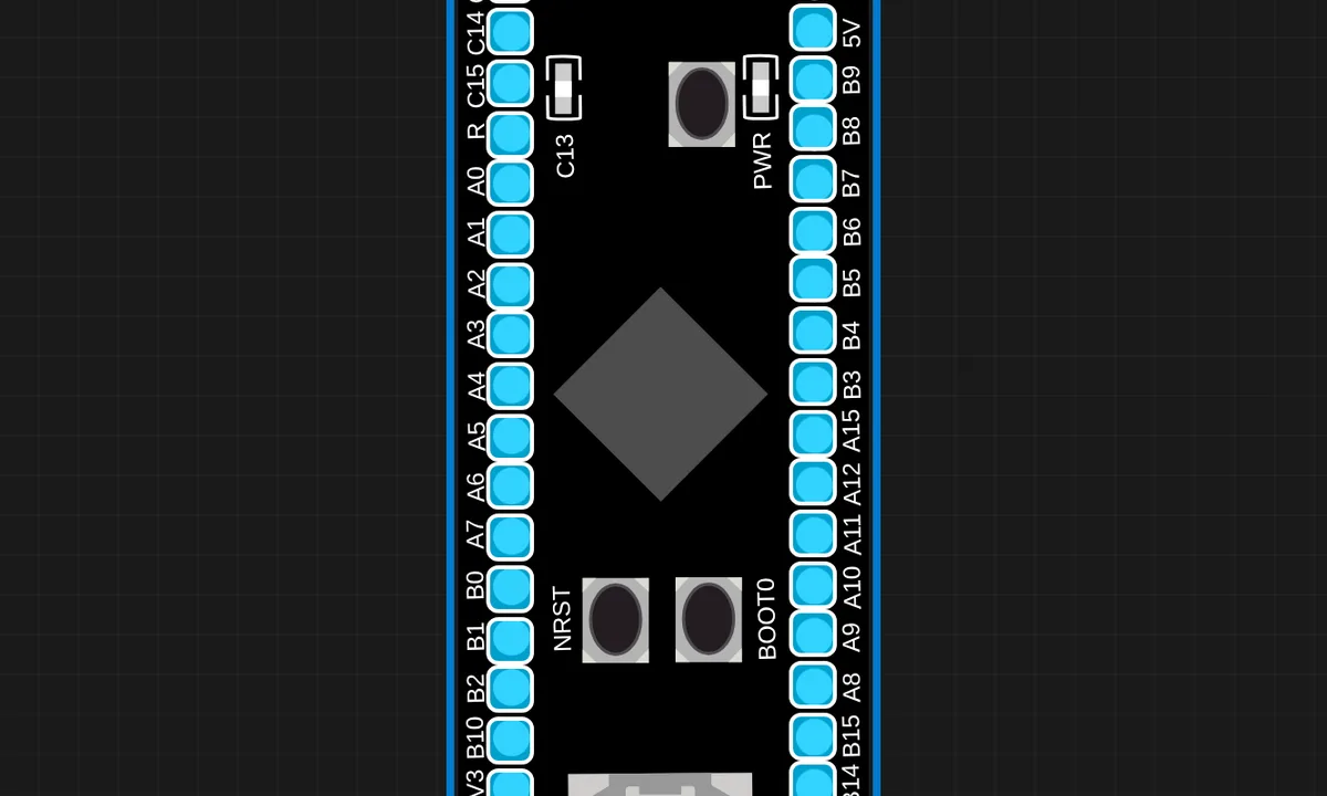
STM32 Black Pill Blink
Blink the onboard PC13 LED and print to Serial on an STM32F411 Black Pill (Cortex-M4, QEMU / libqemu-arm).
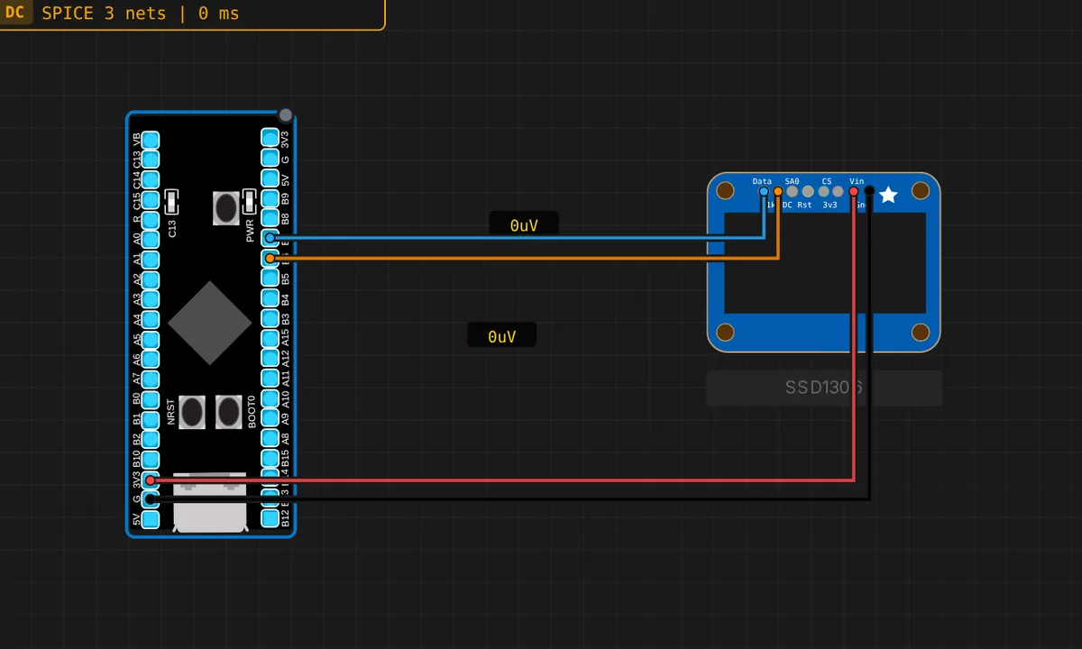
STM32 Black Pill: SSD1306 OLED (I2C)
Drive a 128x64 SSD1306 OLED over I2C1 from an STM32 Black Pill (F411, Cortex-M4; SCL=PB6, SDA=PB7). Proves the I2C display path works on the F4 board too. Shows "Black Pill" with a live counter.
ATtiny85: Blink LED
Blink an external LED on PB1 (Digispark pin 1) through a 220 Ohm current-limit resistor.
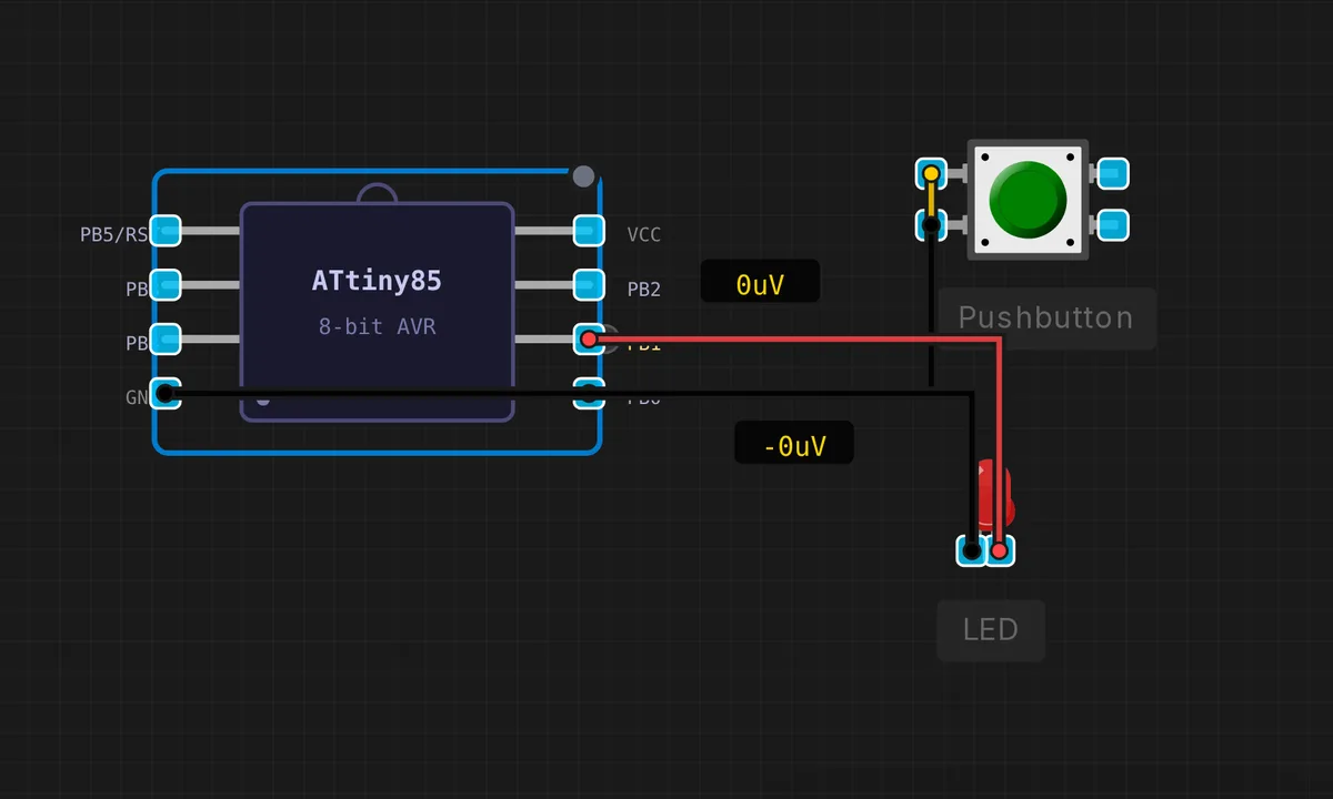
ATtiny85: Button + LED
Press the button on PB0 to light the LED on PB1. Uses internal pull-up resistor — no external resistor needed.
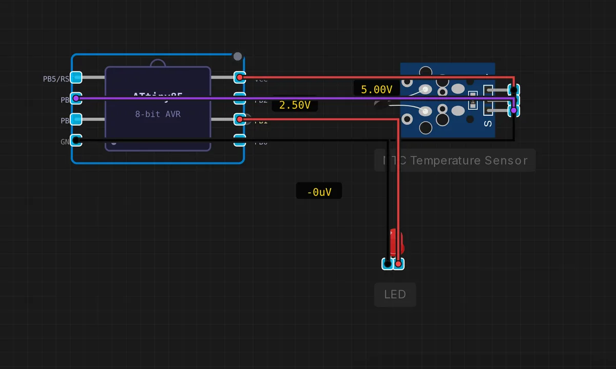
ATtiny85: NTC Temperature Sensor
Read temperature from an NTC thermistor on PB3 (ADC3). The LED on PB1 blinks faster as temperature rises.
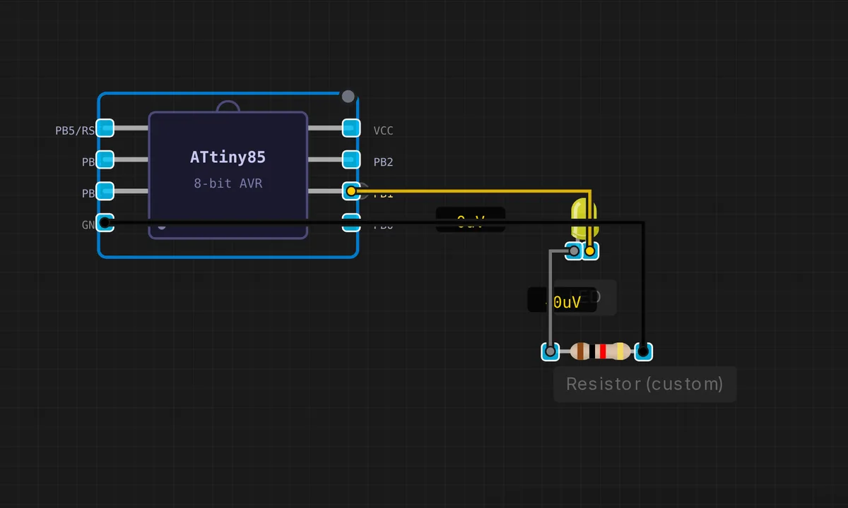
ATtiny85: PWM LED Fade
Smoothly fade an LED in and out using analogWrite() on PB1 (OC0B). Shows Timer0 PWM on the ATtiny85.
![[Pi + Arduino] Serial LED Control](/examples-thumbs/pi-to-arduino-led-control.webp)
[Pi + Arduino] Serial LED Control
Raspberry Pi 3B controls two LEDs on an Arduino Uno via UART serial. Pi sends commands (LED1_ON, LED2_ON…) from a Python script; Arduino parses them and drives the LEDs.
![[Pi 3] Blink an LED](/examples-thumbs/pi3-blink-led.webp)
[Pi 3] Blink an LED
Raspberry Pi 3 blinks a red LED on GPIO17 with gpiozero. Start the Pi, click Upload in the File System panel, then run: python3 /home/pi/script.py
![[Pi 3] Running Lights (5 LEDs)](/examples-thumbs/pi3-running-lights.webp)
[Pi 3] Running Lights (5 LEDs)
Raspberry Pi 3 sweeps a Knight-Rider pattern across 5 LEDs on GPIO17/27/22/5/6 with gpiozero. Start the Pi, Upload, then run: python3 /home/pi/script.py
![[Pi 4] Button Toggles LED](/examples-thumbs/pi4-button-led.webp)
[Pi 4] Button Toggles LED
Raspberry Pi 4 reads a push button on GPIO2 and toggles an LED on GPIO17 with gpiozero. Start the Pi, Upload, run python3 /home/pi/script.py, then click the button.
![[Pi 4] RGB LED Color Cycle](/examples-thumbs/pi4-rgb-color-cycle.webp)
[Pi 4] RGB LED Color Cycle
Raspberry Pi 4 cycles a common-cathode RGB LED through 7 colors using digital on/off on GPIO17/27/22 (gpiozero RGBLED, pwm=False). Start the Pi, Upload, run python3 /home/pi/script.py
![[Pi 5] PIR Motion Alarm](/examples-thumbs/pi5-pir-motion-alarm.webp)
[Pi 5] PIR Motion Alarm
Raspberry Pi 5 lights an LED on GPIO17 whenever a PIR motion sensor on GPIO4 detects movement (gpiozero MotionSensor). Start the Pi, Upload, run python3 /home/pi/script.py, then trigger the PIR.
![[Pi 5] Traffic Light](/examples-thumbs/pi5-traffic-light.webp)
[Pi 5] Traffic Light
Raspberry Pi 5 runs a red/yellow/green traffic-light state machine on GPIO17/27/22 with gpiozero. Start the Pi, Upload, then run: python3 /home/pi/script.py
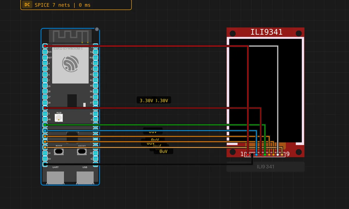
ILI9341 TFT Hello — ESP32-S3
Draws a filled screen, a rounded rectangle and text on a 320x240 ILI9341 TFT from an ESP32-S3 over hardware SPI (FSPI / GPSPI2).
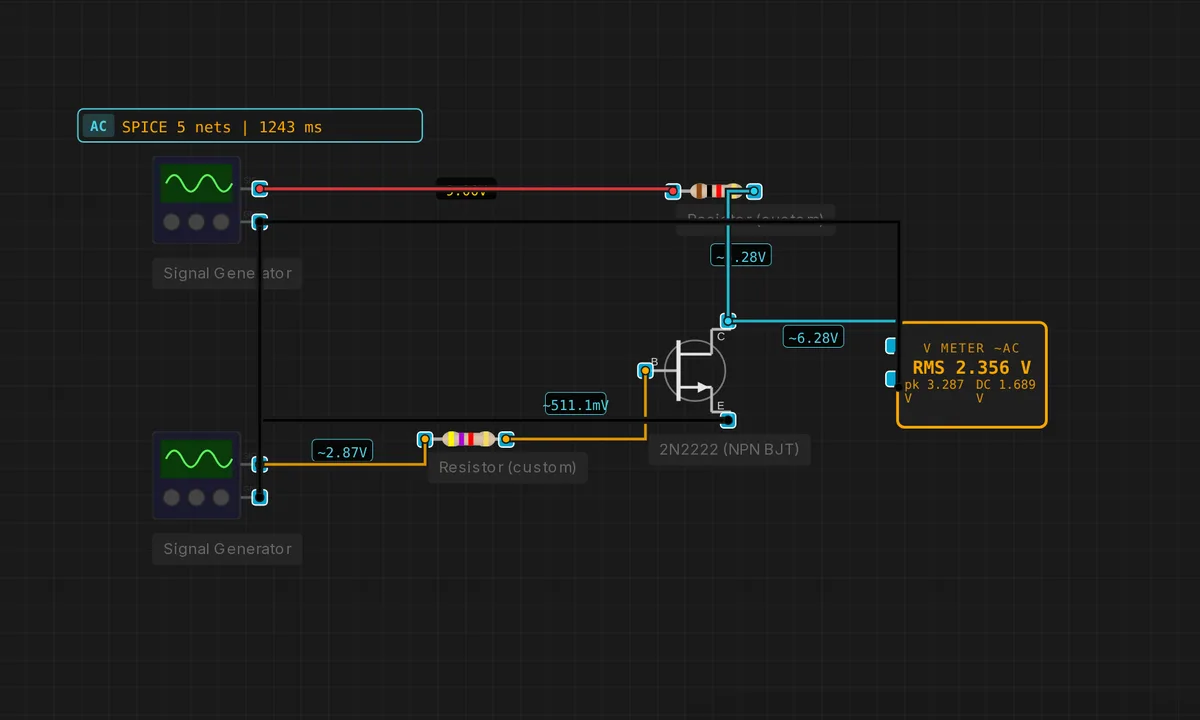
BJT as a Switch
Base driven into saturation through Rb; collector pulled up via a load resistor. DC step input toggles Vce between ~0.2 V and Vcc.
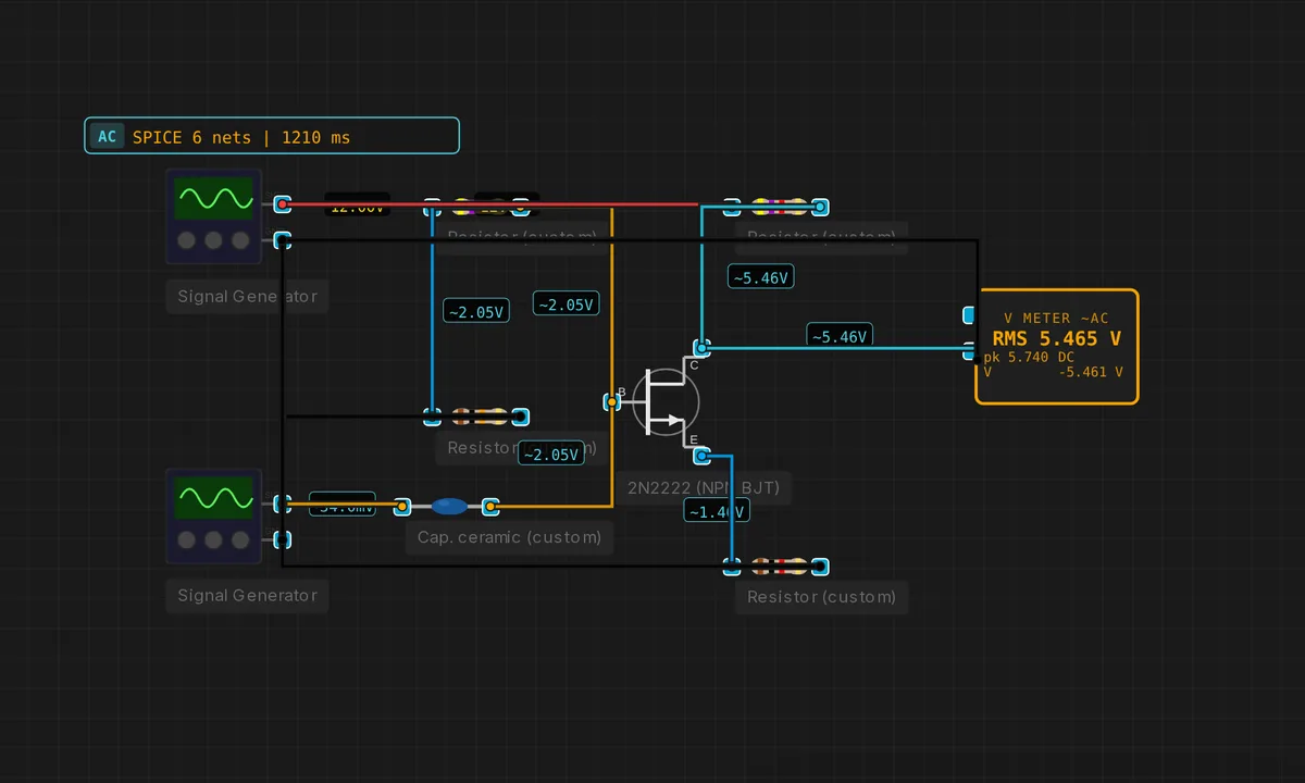
BJT Common-Emitter Amplifier
Classic voltage amplifier: base biased by a divider, emitter degenerated by Re, collector resistor sets gain.
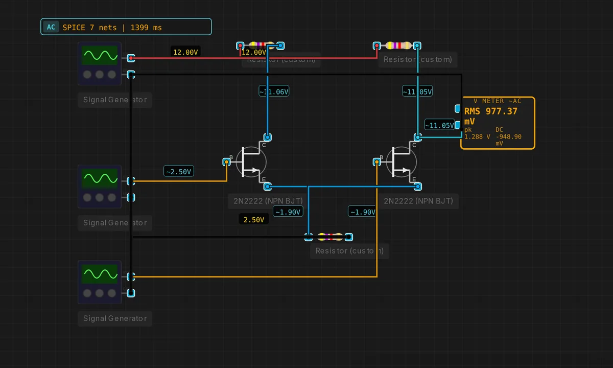
BJT Differential Pair
Long-tailed pair: a shared emitter tail resistor steers current between Q1 and Q2 according to the differential input.
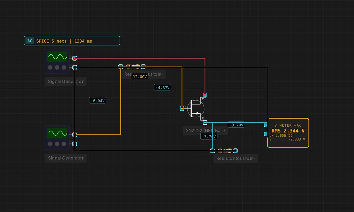
BJT Emitter Follower
Common-collector buffer: unity voltage gain, high input impedance, low output impedance. Great as a driver stage.
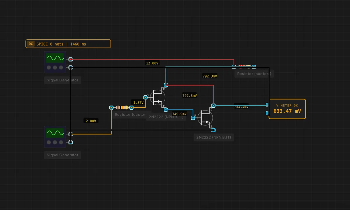
Darlington Pair
Two cascaded NPNs multiply β — β_total ≈ β1·β2. Used when a single transistor can’t supply enough base current for a heavy load.
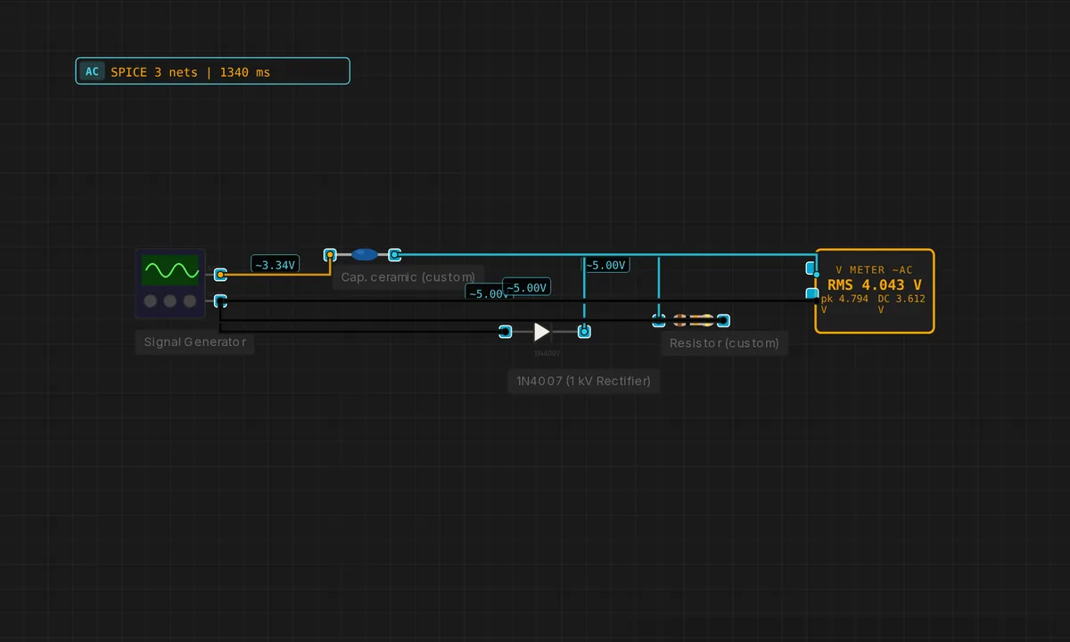
Diode Clamper (DC Restorer)
Series cap + parallel diode shifts the signal so its negative peak sits at 0 V. Output swings 0 → 2·Vpeak.
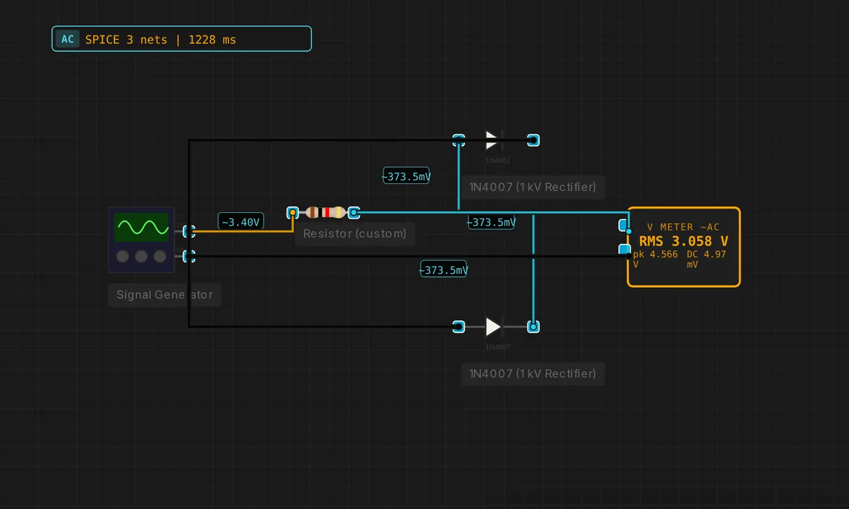
Diode Clipper
Two diodes to VCC/GND via a series resistor limit the output swing to roughly ±0.7 V — symmetric clipping.
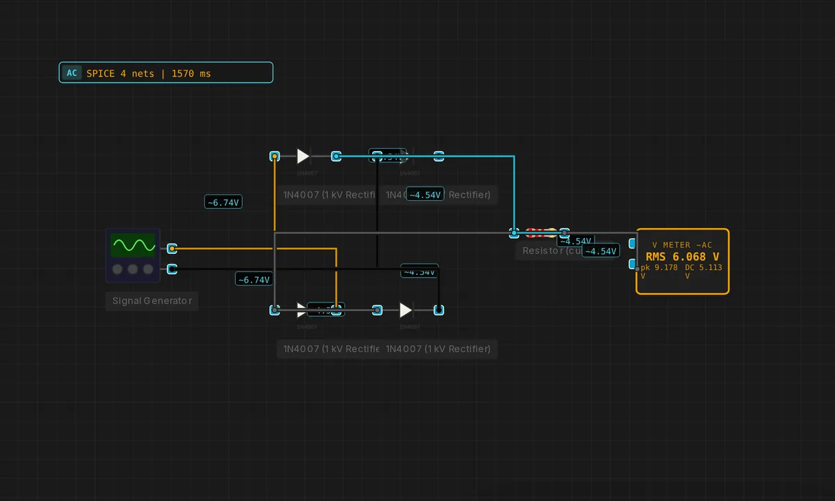
Full-Wave Bridge Rectifier
Four diodes in a bridge rectify both halves of the AC input. Load R1 sees full-wave pulses at 2× the input frequency.
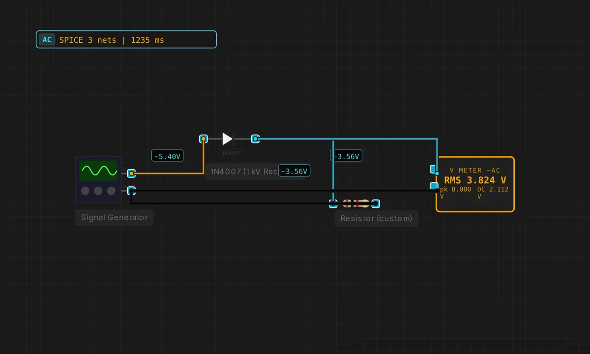
Half-Wave Rectifier
Single diode passes only the positive half-cycle of a 50 Hz sine. Load resistor drops the rectified voltage.
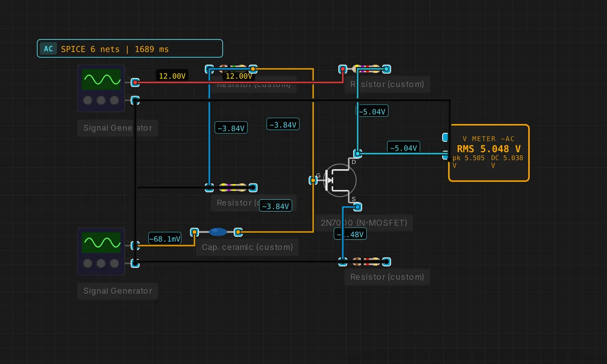
MOSFET Common-Source Amplifier
2N7000 as a small-signal amp: drain resistor sets gain, source resistor stabilises bias. AC-coupled signal input.
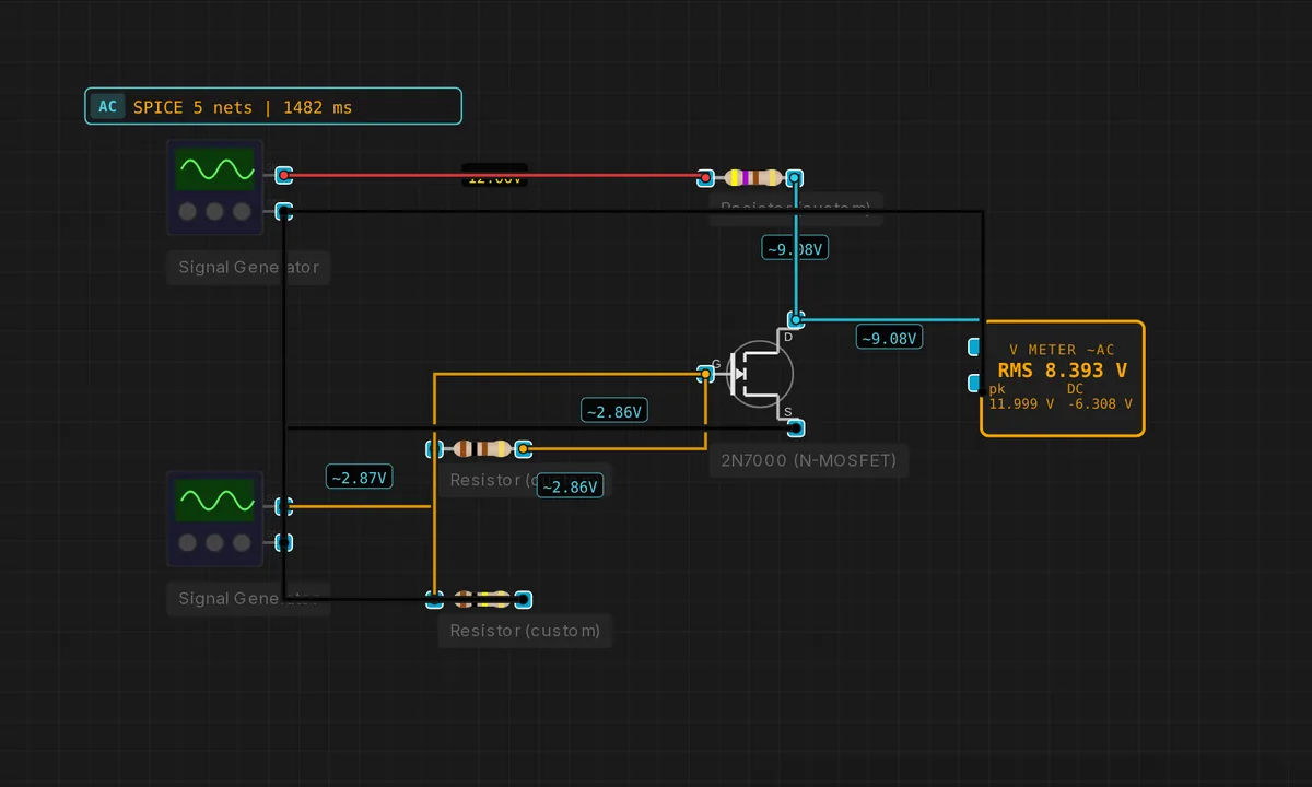
MOSFET Low-Side Switch
2N7000 NMOS with a pull-down gate resistor. Gate drive above Vth turns the device on and sinks current from the load to GND.
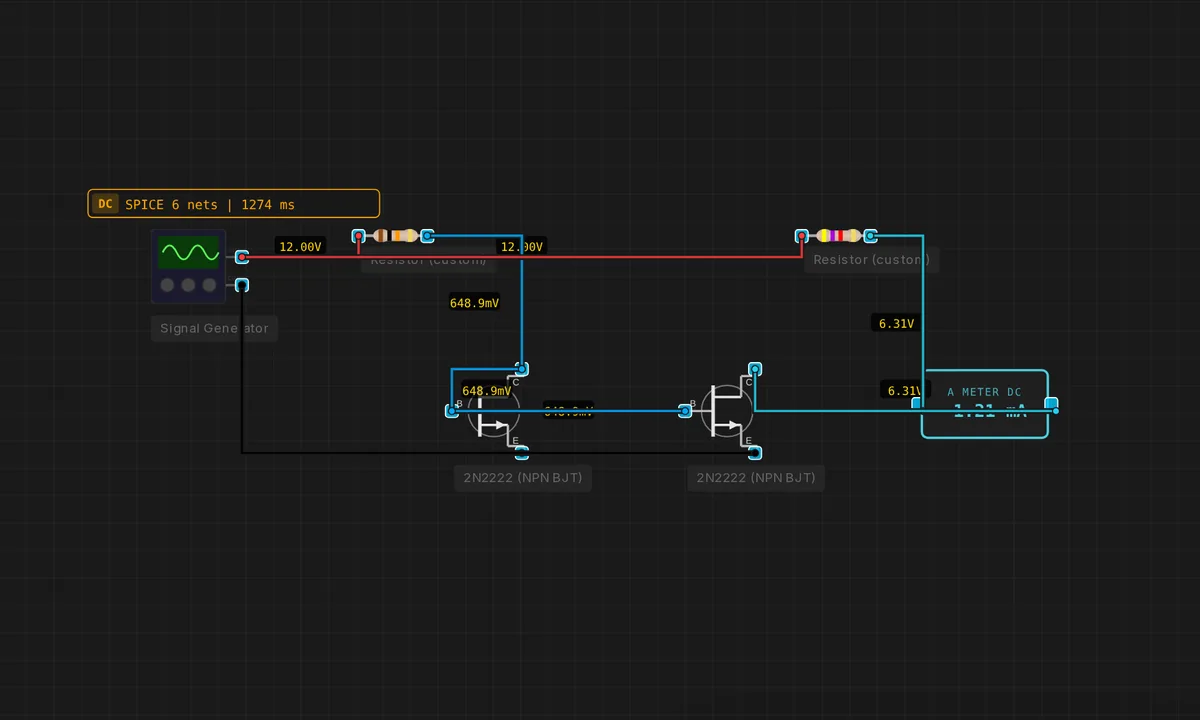
NPN Current Mirror
Reference current in Q1 is mirrored through Q2’s collector — matched transistors + shared Vbe make the collector currents equal.
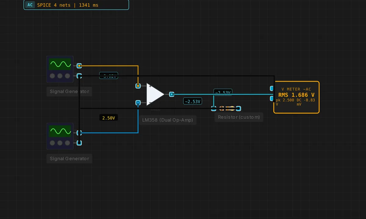
Op-Amp Comparator
Open-loop op-amp compares V_in against a reference. Output saturates high when IN+ > IN-, low otherwise.
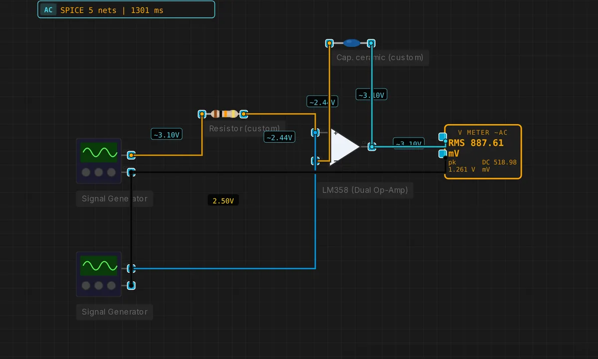
Op-Amp Integrator
Rf replaced by a cap: V_out = −(1/RC) ∫V_in dt. Square-wave in → triangle-wave out. Classic analog-computer building block.
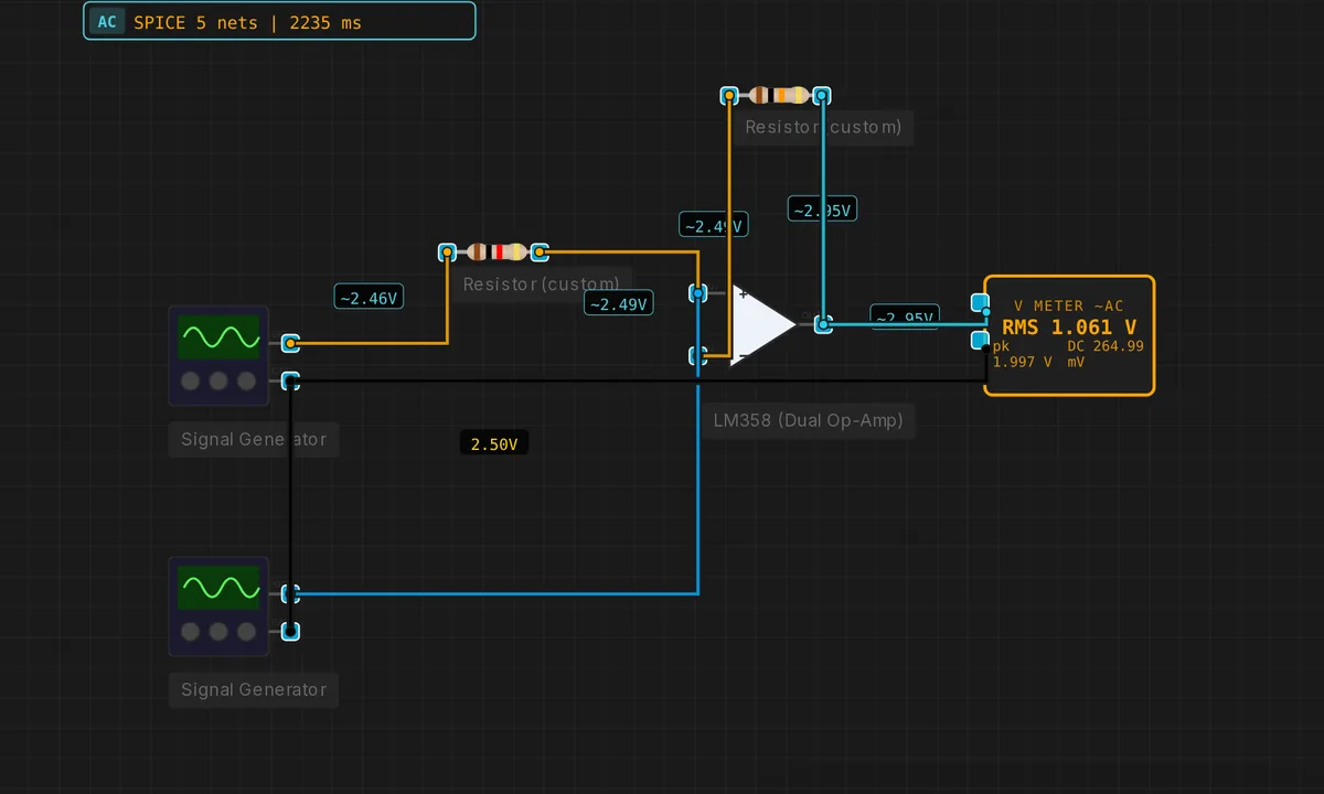
Op-Amp Inverting Amplifier
Gain = −Rf/Rin. Rf = 10 k, Rin = 1 k → gain = −10. LM358 single-supply model clamps the output to [0, VCC−1.5].
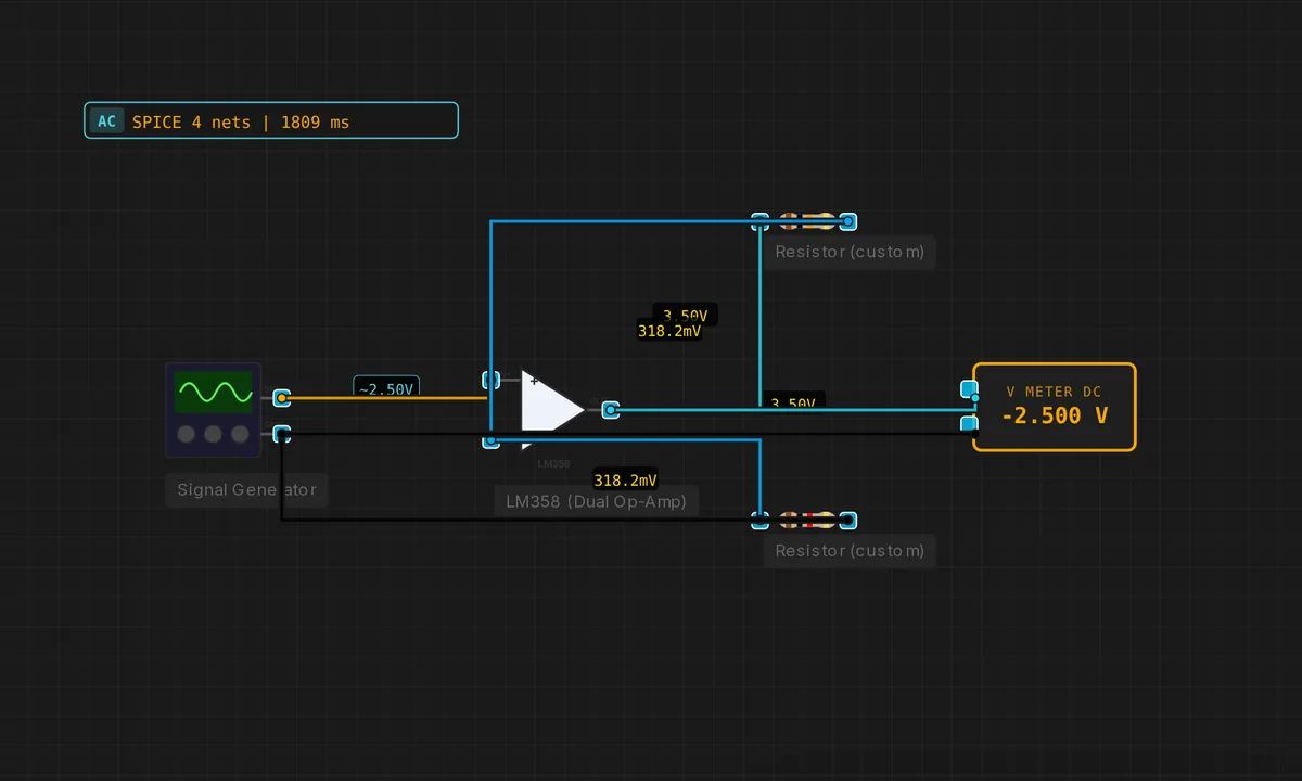
Op-Amp Non-Inverting Amplifier
Gain = 1 + Rf/Rg. Rf = 10 k, Rg = 1 k → gain = +11. Output in-phase with input.
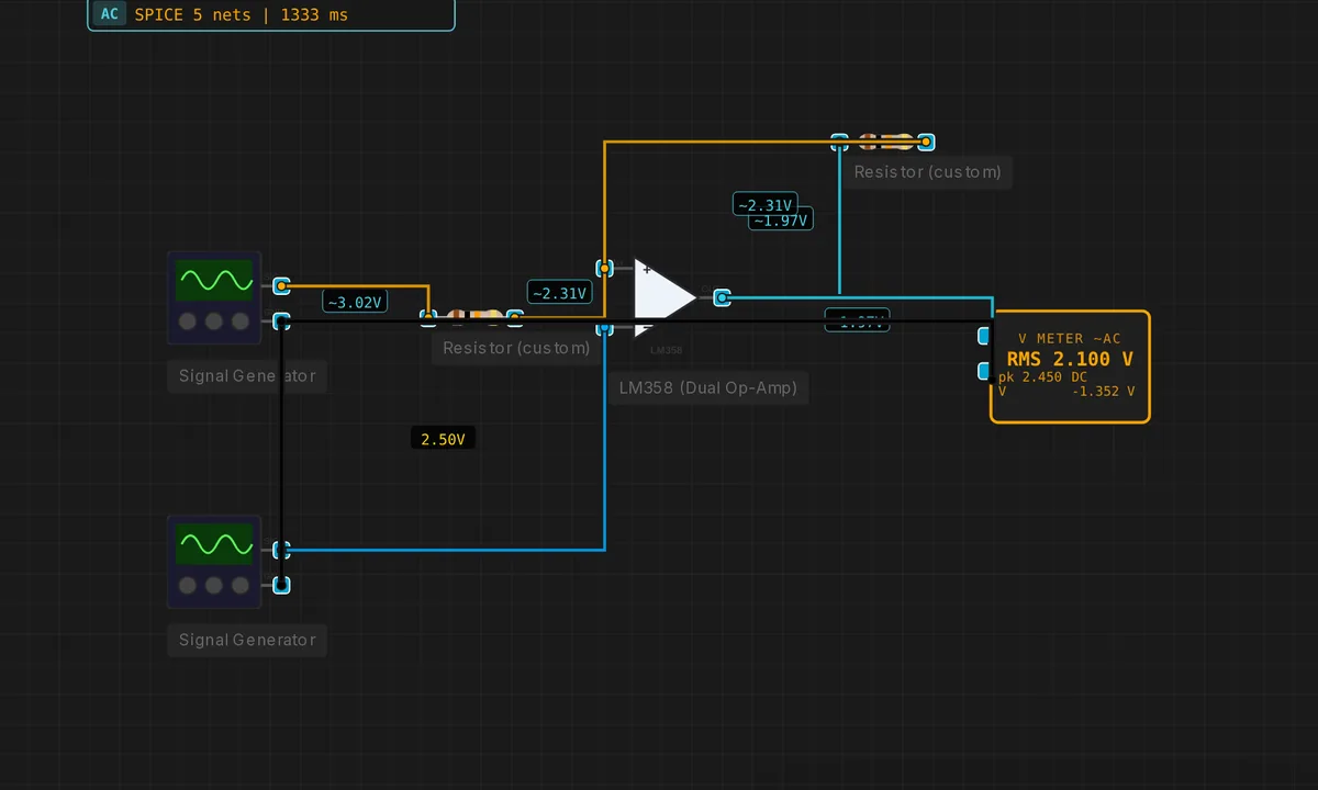
Op-Amp Schmitt Trigger
Positive feedback (R2 from OUT to IN+) adds hysteresis: two switching thresholds instead of one. Cleans up noisy signals.
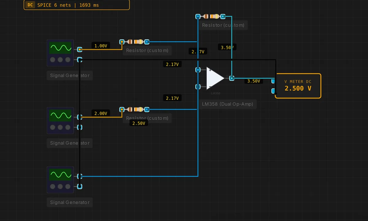
Op-Amp Summing Amplifier
Virtual-ground summing junction: V_out = −Rf · (V1/R1 + V2/R2). Two-input mixer with unity gain per channel.

Op-Amp Voltage Follower
Unity-gain buffer: output tracks the non-inverting input exactly. Infinite input impedance, near-zero output impedance.
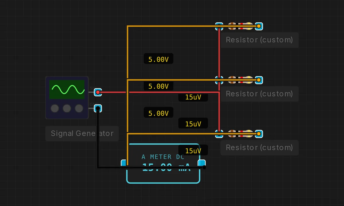
Parallel Resistors
Three resistors in parallel — total resistance is the reciprocal of the reciprocal sum. Ammeter shows total current.
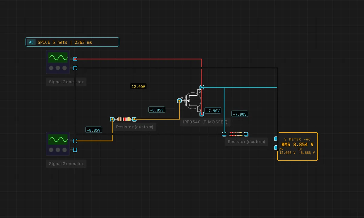
PMOS High-Side Switch
P-channel MOSFET (IRF9540) sources current from VCC when the gate is pulled below VCC−|Vth|. Ideal for load switching.
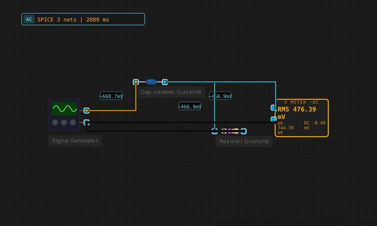
RC High-Pass Filter
Swap the R and C of a low-pass and you get a high-pass. 1 kHz sine through C — R — GND.
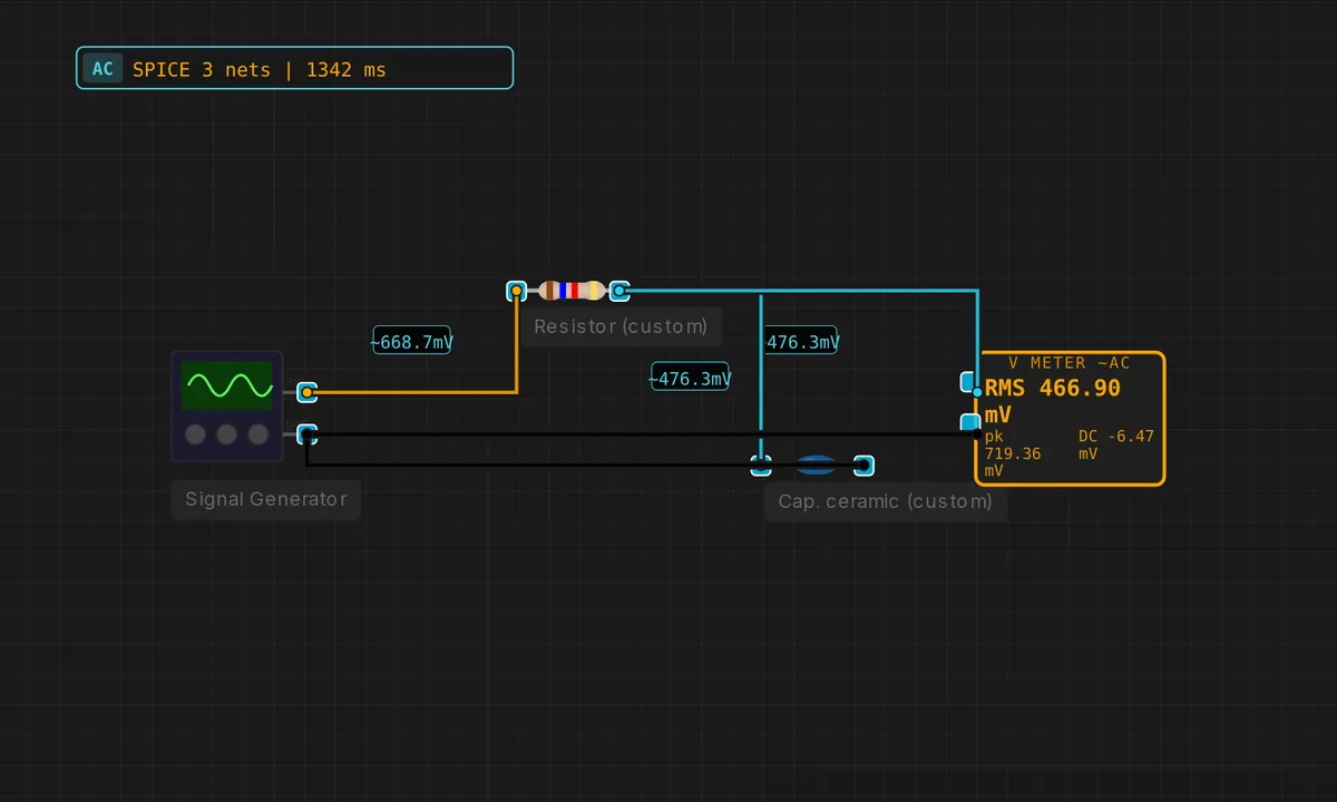
RC Low-Pass Filter
1 kHz sine through R = 1.6 kΩ and C = 100 nF. fc ≈ 1 kHz — output attenuated by −3 dB.
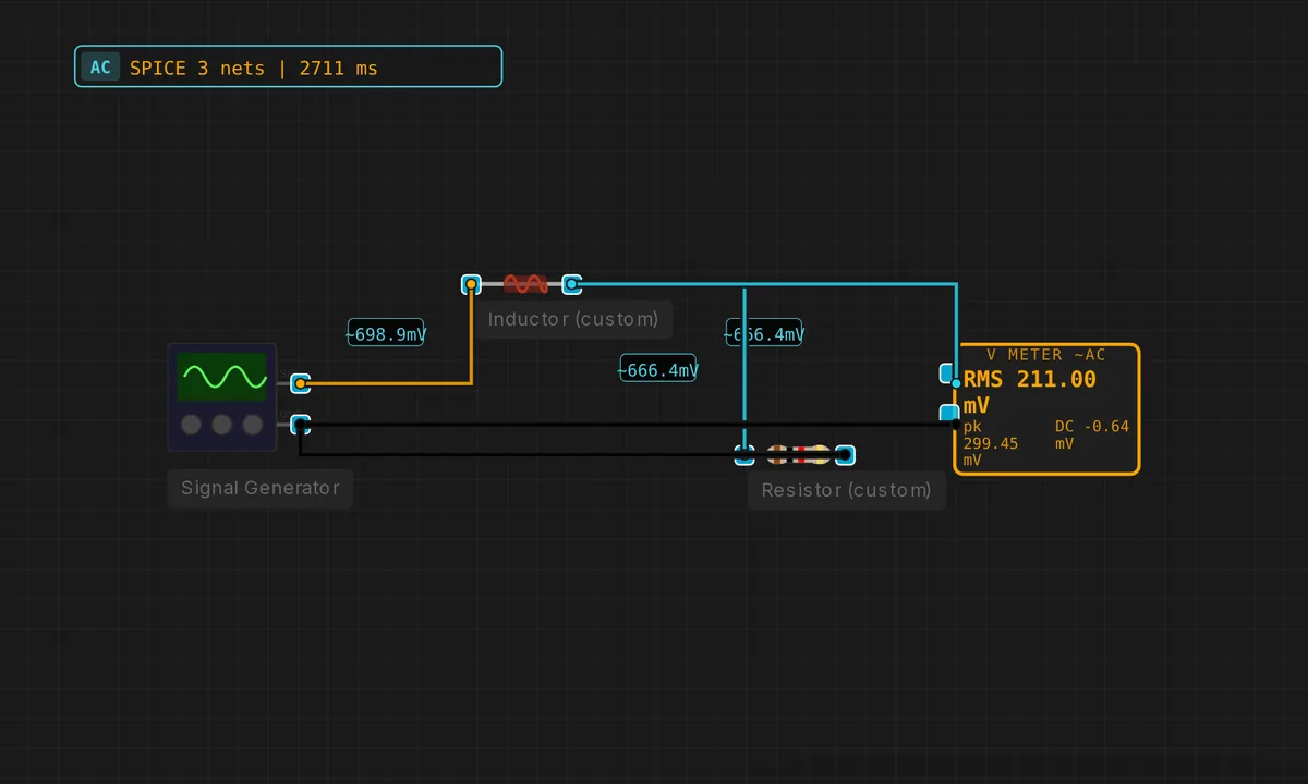
RL Low-Pass Filter
Inductor in series, resistor to ground. High frequencies dropped across L; low frequencies pass through.
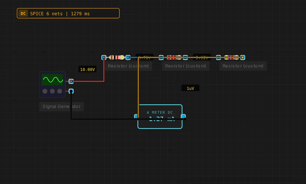
Series Resistors
Three resistors in series carry the same current — ammeter reads V/(R1+R2+R3).
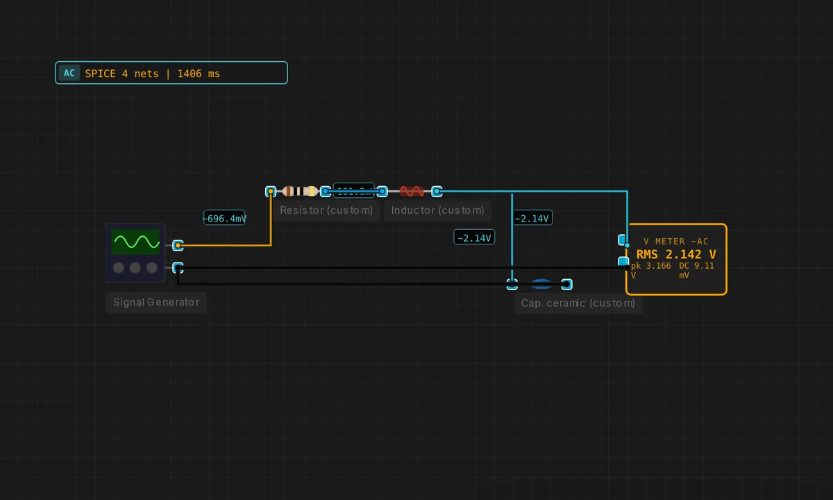
Series RLC Resonant Circuit
L = 1 mH, C = 1 µF gives fr ≈ 5 kHz. Sweep the signal generator — Vc peaks at resonance (Q-dependent).
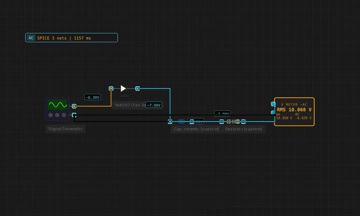
Smoothed Half-Wave Rectifier
Half-wave rectifier followed by a 100 µF reservoir cap. Output is near-DC with ripple inversely proportional to C.
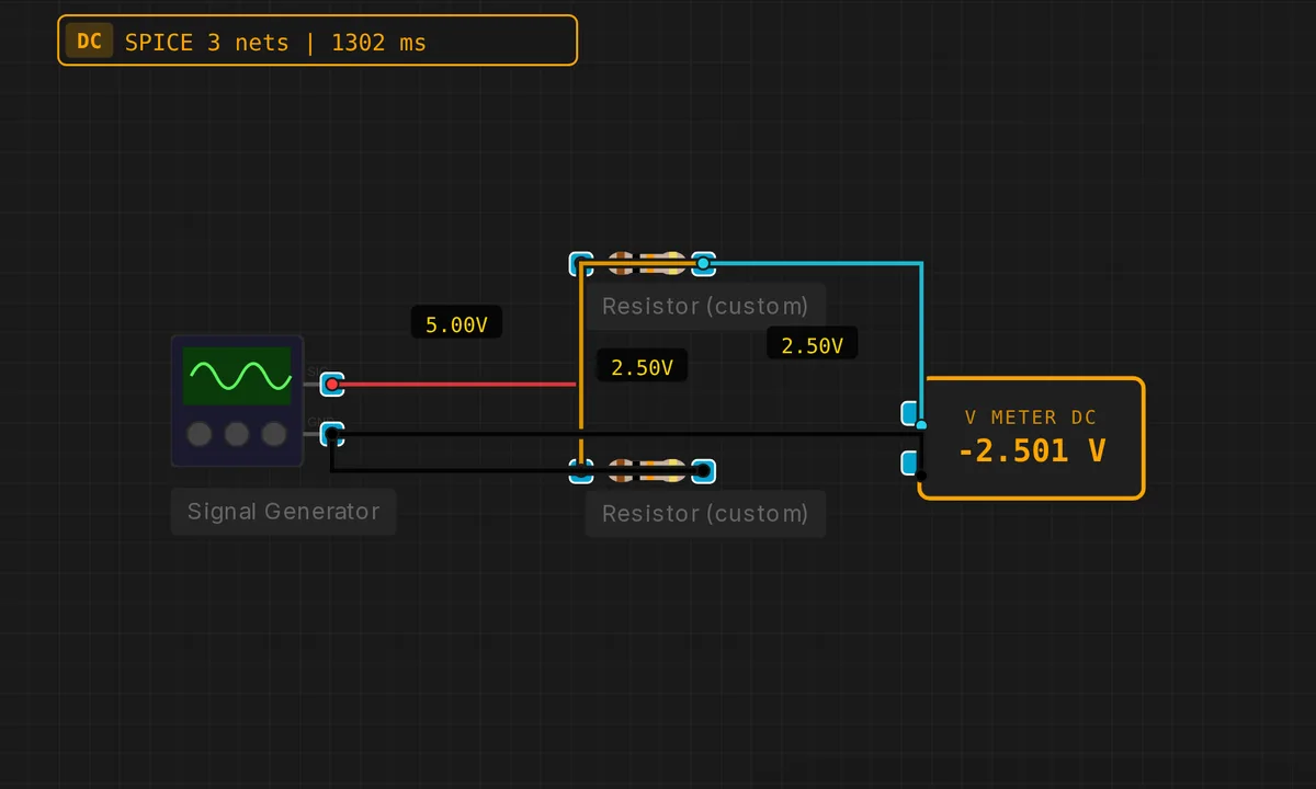
Voltage Divider
Two resistors divide a 5 V DC source in half. Classic first SPICE demo — expect 2.5 V across R2.
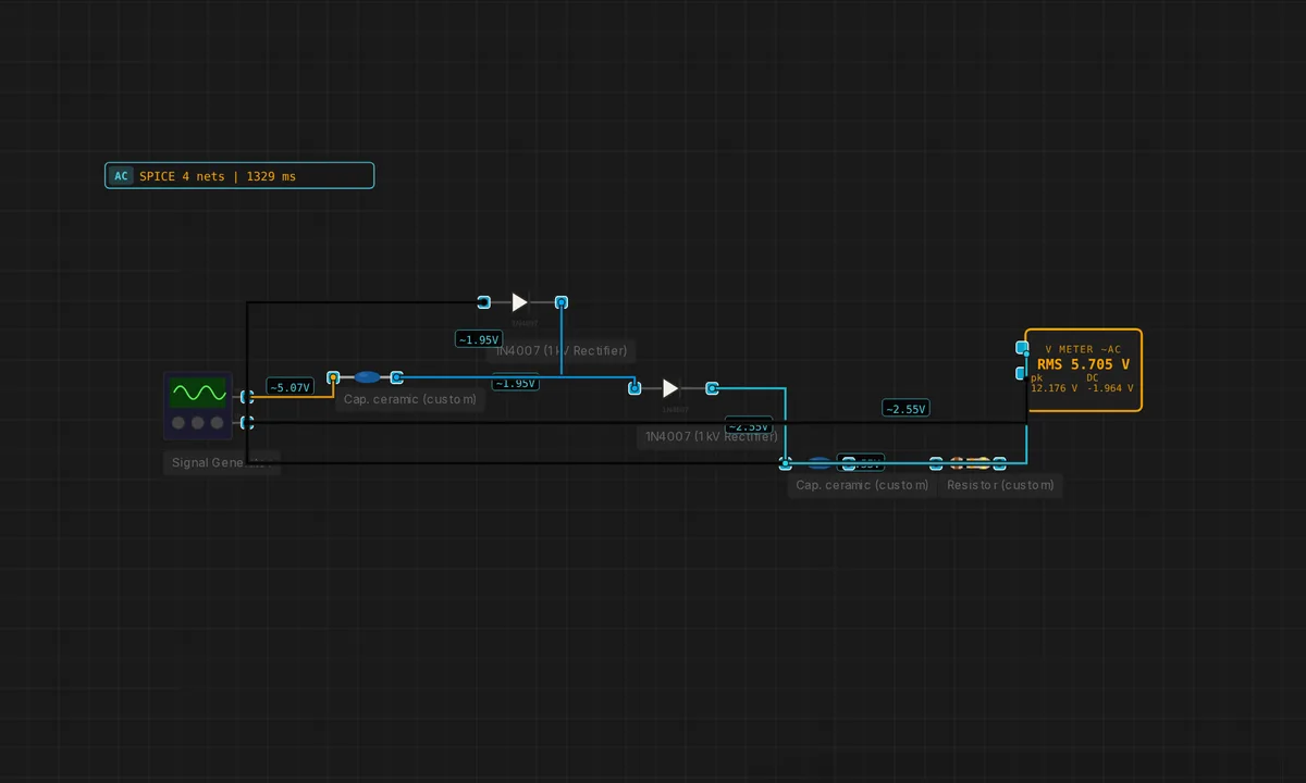
Voltage Doubler (Villard / Greinacher)
Two caps + two diodes extract roughly 2·Vpeak DC from an AC input. First stage clamps, second stage peak-detects.
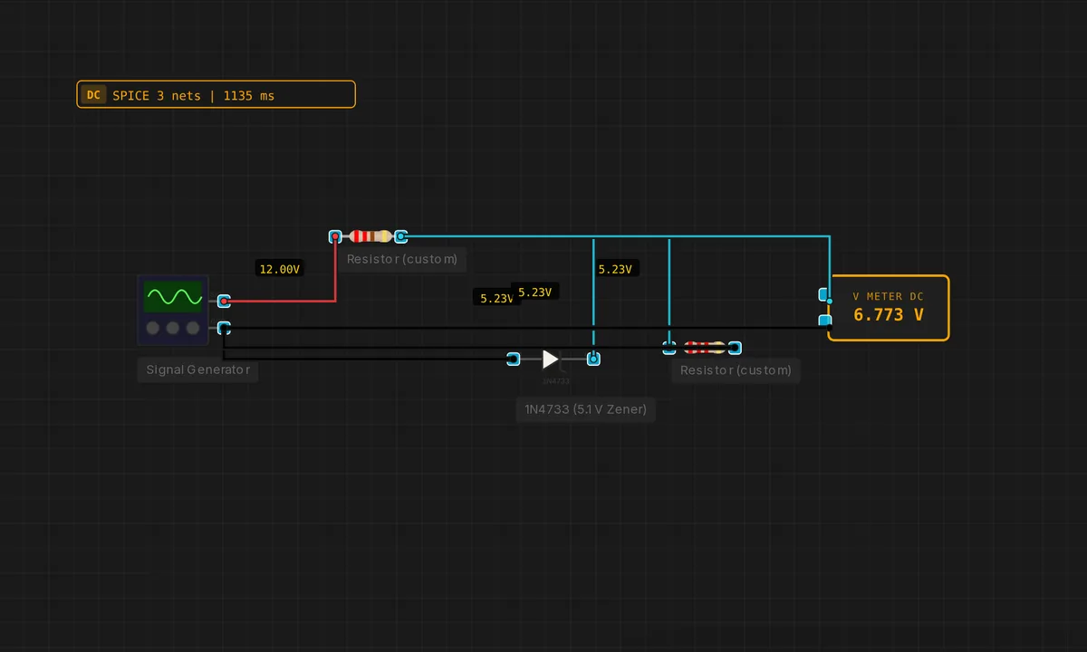
Zener Shunt Regulator
Series resistor + reverse-biased zener clamps the output to Vz (5.1 V for a 1N4733) despite changing input.
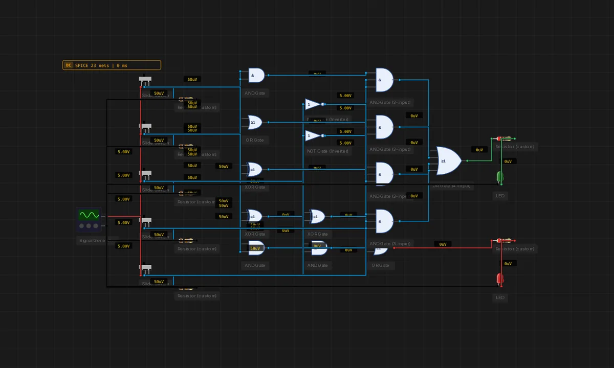
1-Bit ALU Slice (AND / OR / XOR / ADD)
A complete 1-bit ALU cell — AND, OR, XOR and ADD all computed in parallel, with a 4-to-1 MUX selecting which result drives Y. The carry path is wired so the slices cascade into a 32-bit ALU like in MIPS.
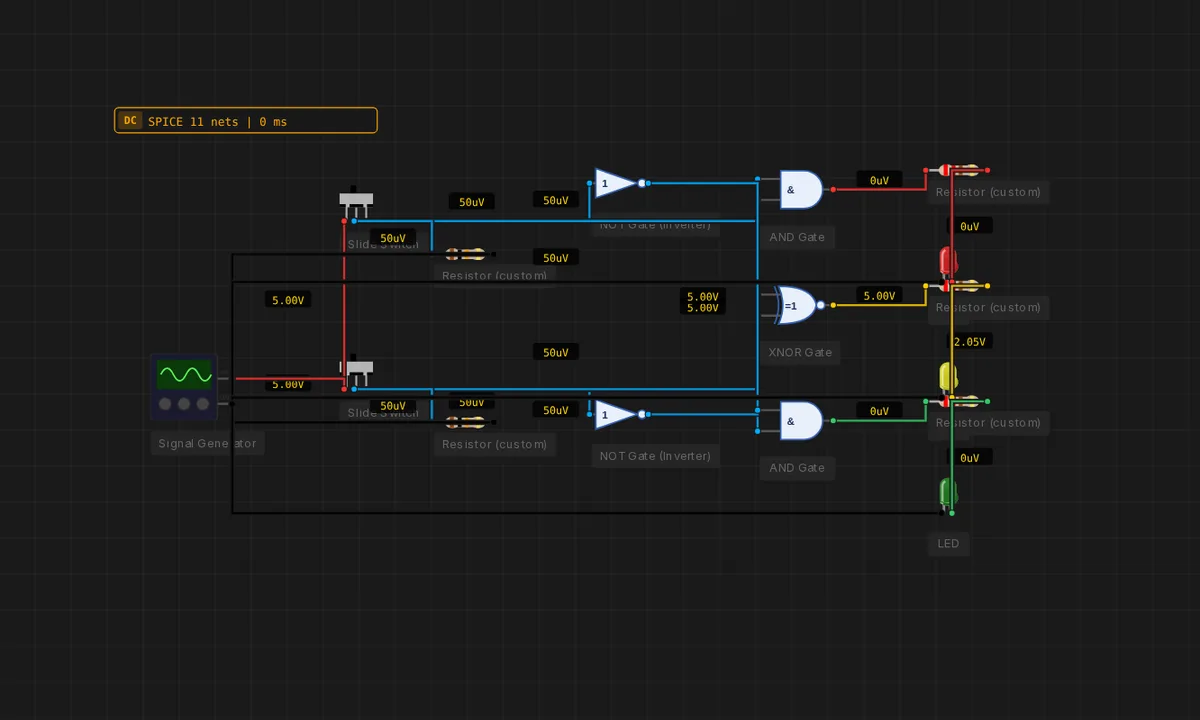
1-Bit Magnitude Comparator
Three outputs decode the relationship between A and B: A>B, A=B, A<B. Built from two NOTs, two ANDs and one XNOR.
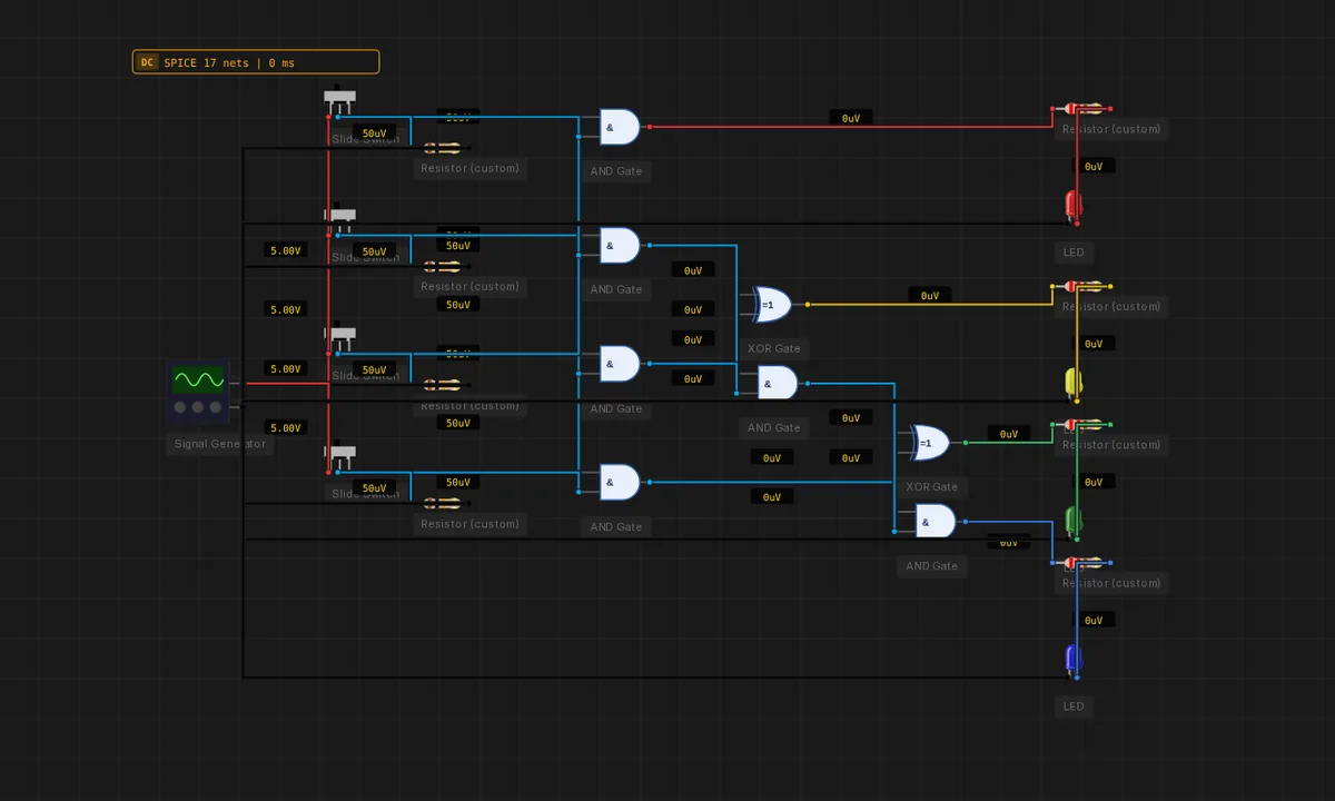
2-Bit × 2-Bit Binary Multiplier
Four AND gates compute the partial products; two half adders sum the columns. The four output LEDs show the 4-bit product P3..P0 of two 2-bit numbers A1A0 × B1B0.
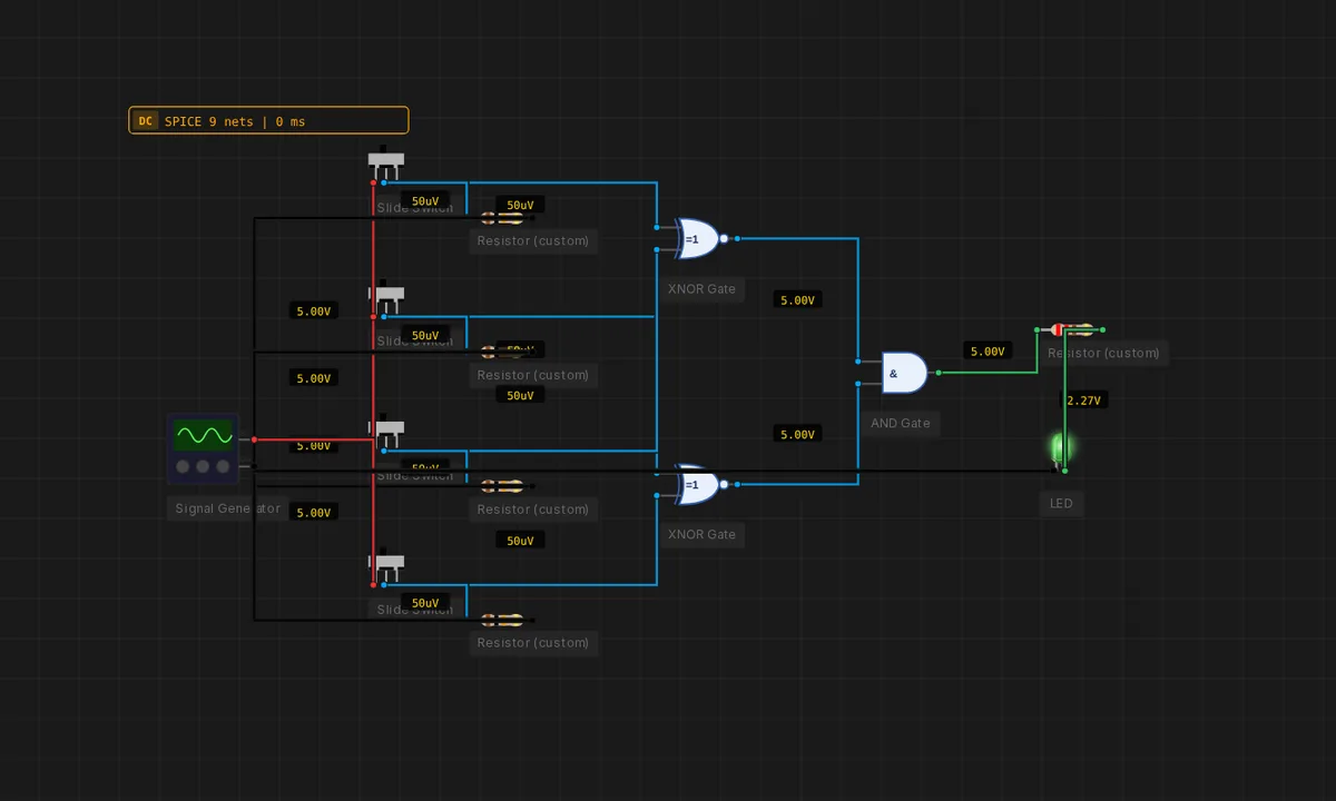
2-Bit Equality Comparator
Two XNORs compare individual bits, an AND combines them. The LED lights only when A1A0 = B1B0.
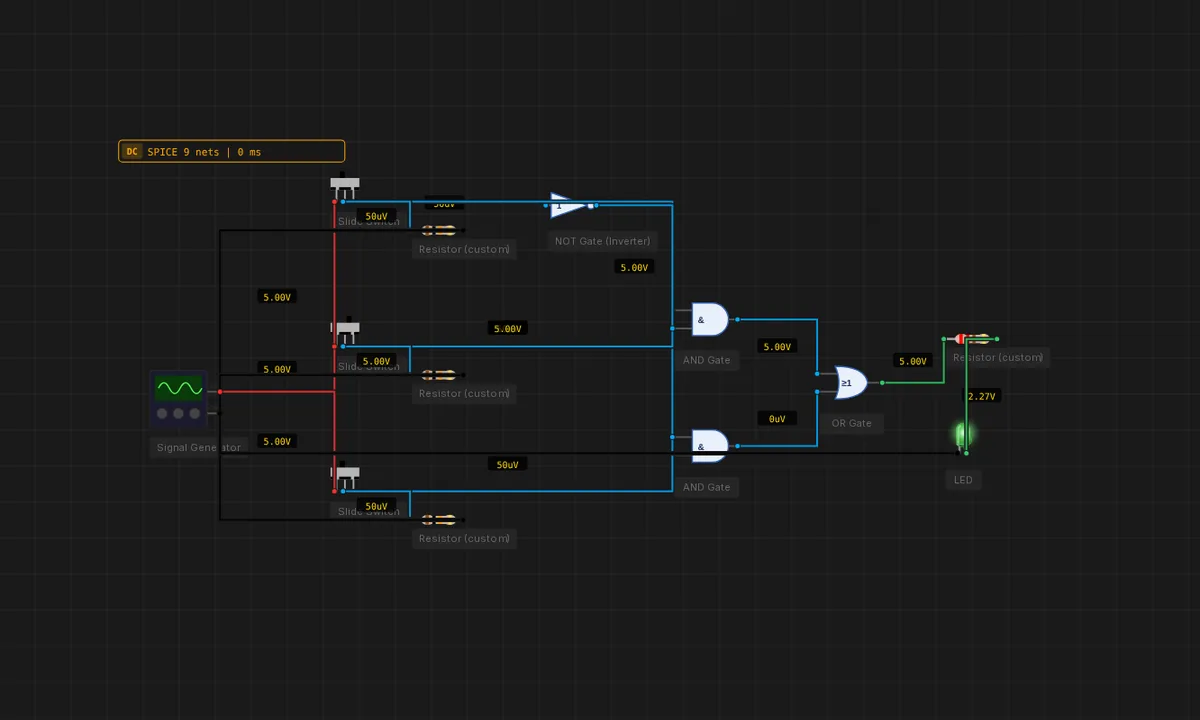
2-to-1 Multiplexer
Two AND gates feed an OR gate. SEL routes either D0 or D1 to Y. The textbook gate-level MUX.
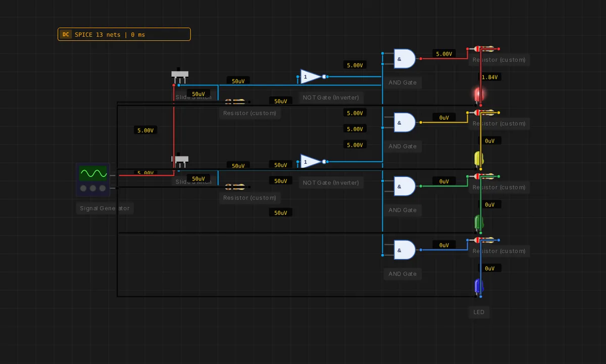
2-to-4 Line Decoder
Two select lines pick exactly one of four outputs. Each output is A·B for some combination of A/!A and B/!B. The backbone of address decoding inside every CPU.
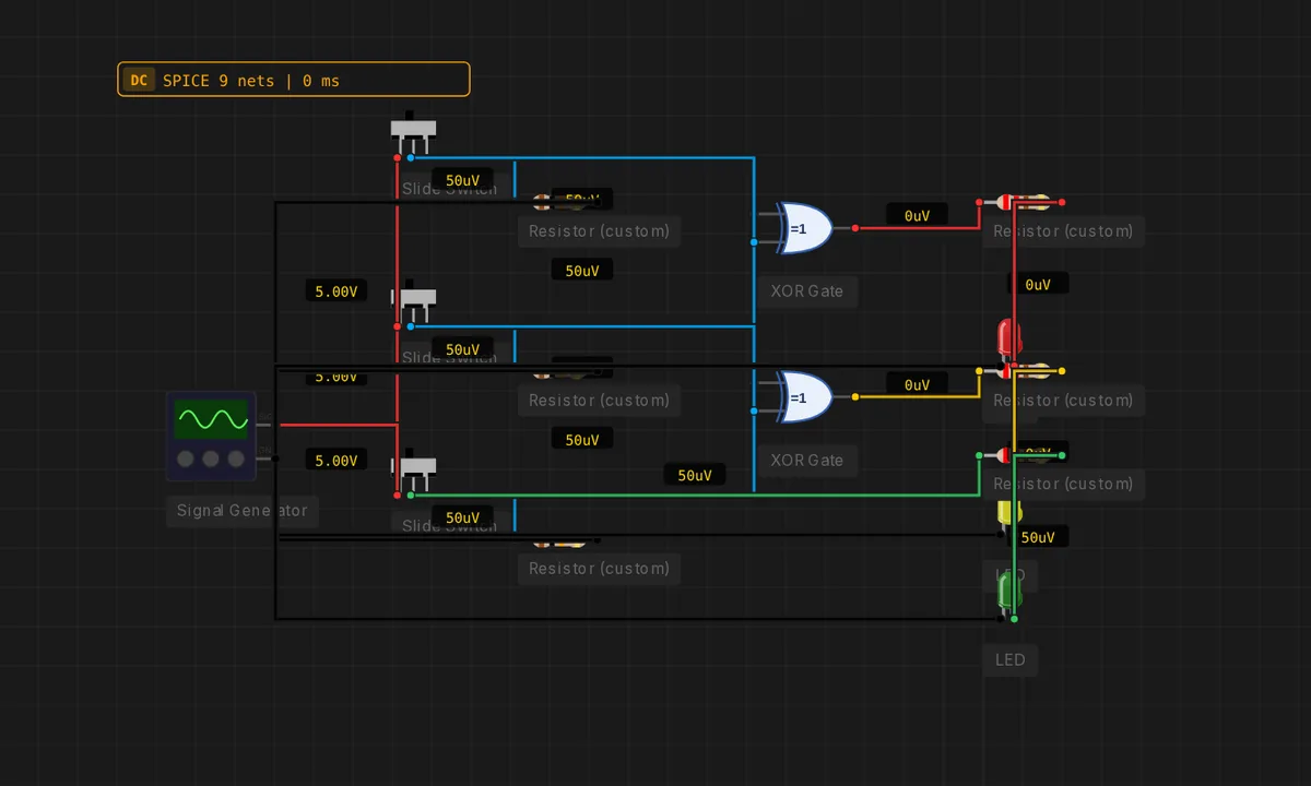
3-Bit Binary → Gray Converter
Two XORs convert a 3-bit binary input to its Gray-code form: G2=B2, G1=B2⊕B1, G0=B1⊕B0. Toggle the input switches and watch only one output flip per increment — the defining property of Gray code.
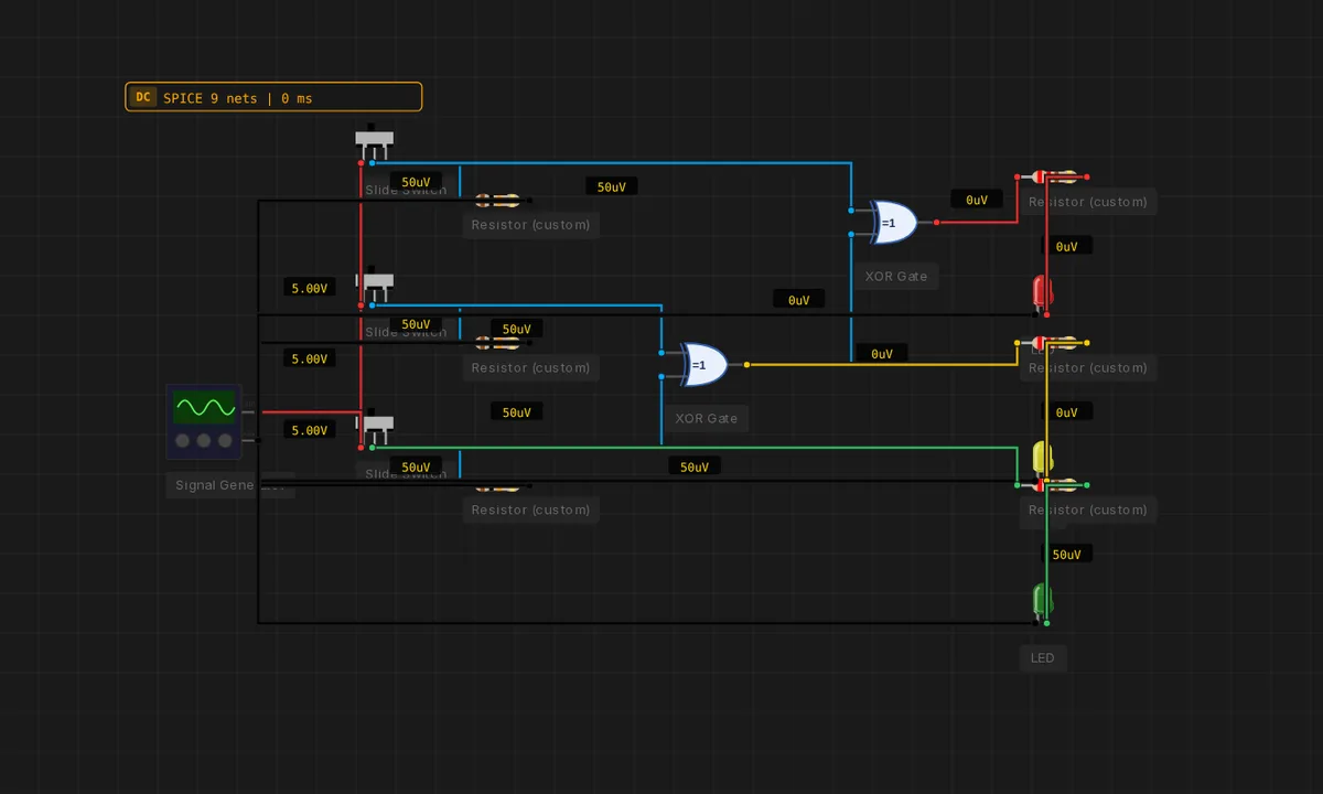
3-Bit Gray → Binary Converter
Inverse of the binary-to-Gray converter — three input switches feed an XOR cascade running from MSB to LSB to recover the binary value.
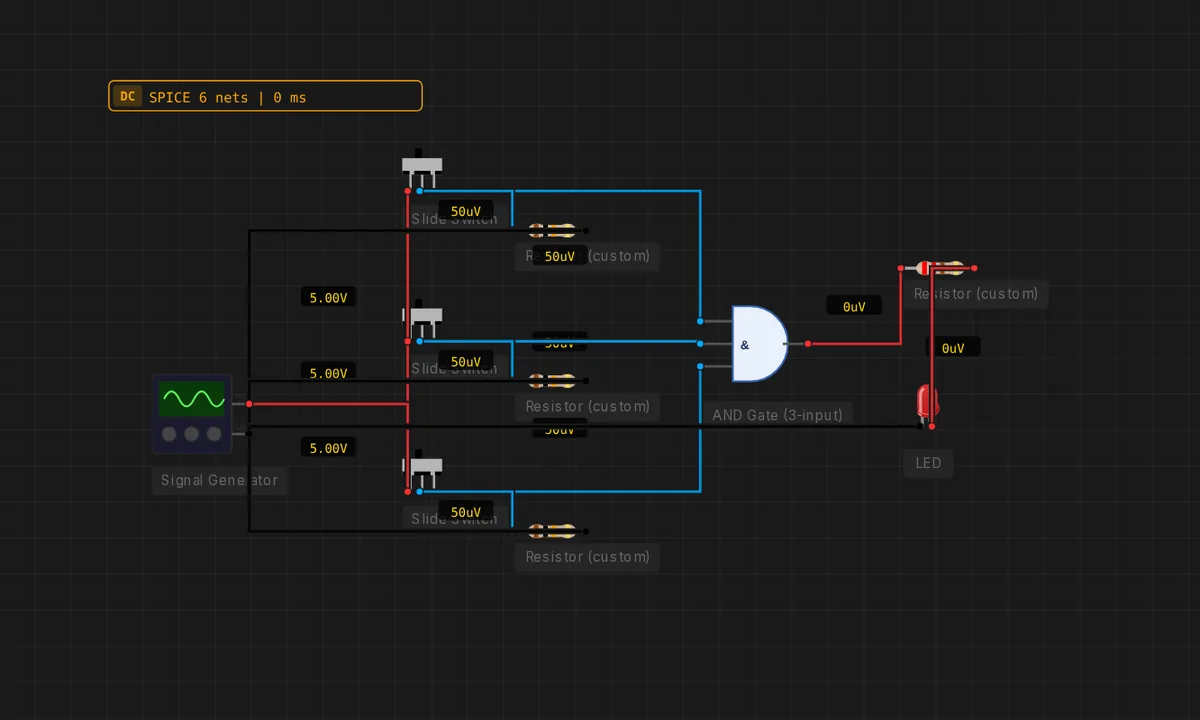
3-Input AND — All Three
Three slide switches drive a 3-input AND. The LED stays dark until every switch is HIGH at the same time.
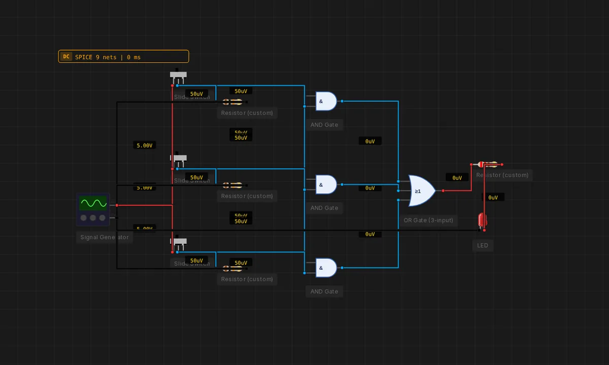
3-Input Majority Voter
Output is HIGH when at least 2 of 3 inputs are HIGH: Y = AB + AC + BC. Fault-tolerant logic in seven gates.
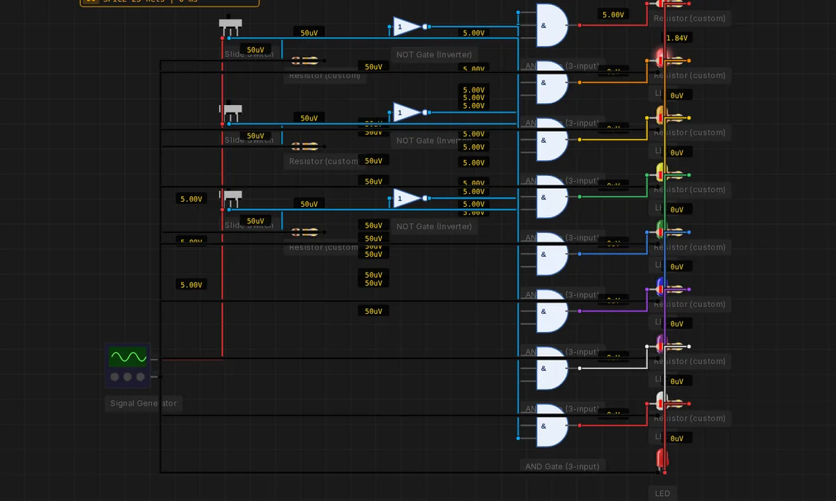
3-to-8 Line Decoder
Three select bits drive eight outputs — exactly one LED lights at a time. The lit LED is the binary value of A2A1A0. Eight 3-input ANDs and three inverters.
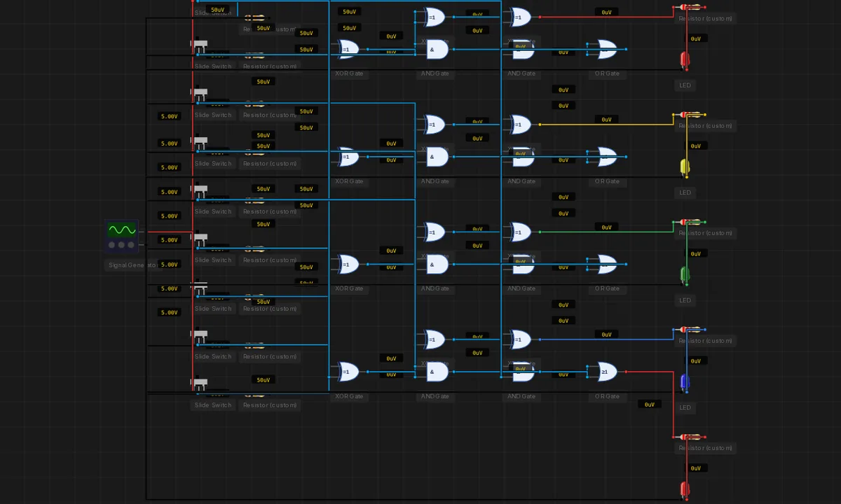
4-Bit Adder / Subtractor
A single mode line selects add (M=0) or subtract (M=1, via two-complement). Each B bit is XOR-ed with M and M also feeds the FA0 carry-in, so the same ripple chain computes A+B or A−B.
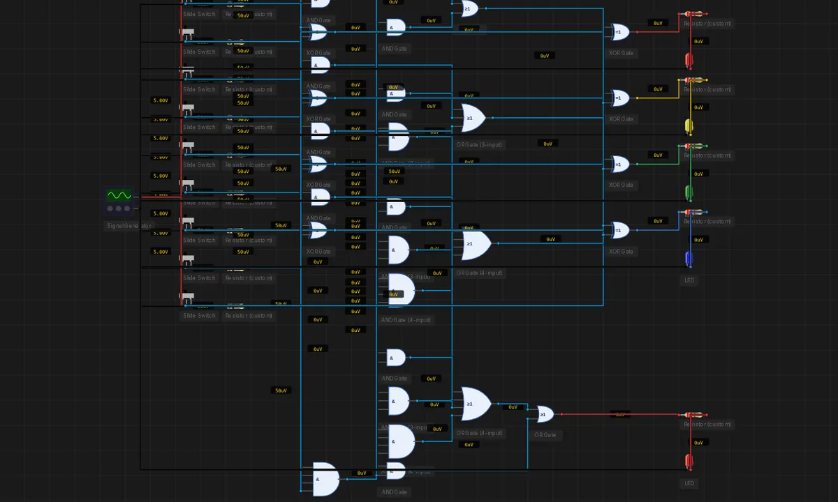
4-Bit Carry-Lookahead Adder
Replaces the ripple chain with a parallel carry network. Generate / propagate signals + four lookahead expansions compute c1..c4 in constant gate-depth — the same O(log n) speedup pattern that scales to 64-bit CPU adders.
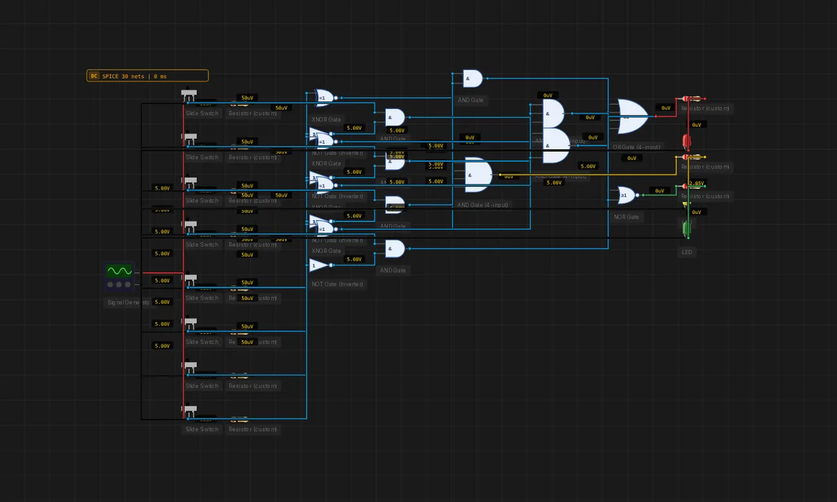
4-Bit Magnitude Comparator
Compares two 4-bit numbers A and B. Four XNORs decide bit equality, a priority cascade of ANDs/ORs decides A>B, and a NOR derives A<B. Three LEDs decode the relationship live.
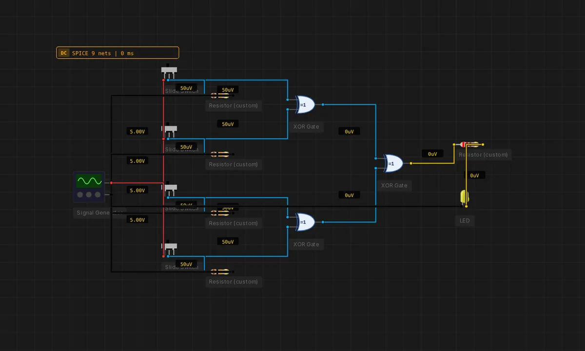
4-Bit Parity Generator
Three cascaded XORs compute the even-parity bit of a 4-bit nibble. The LED is HIGH when an odd number of input switches are HIGH.
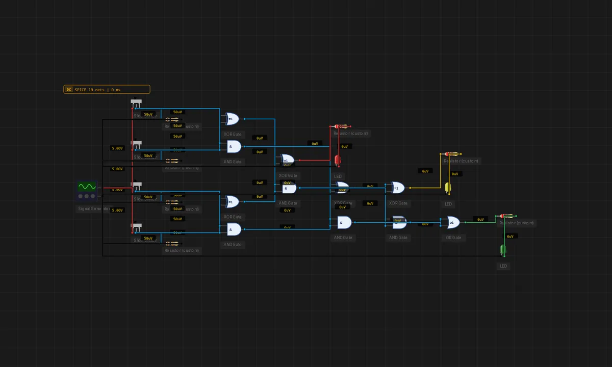
4-Bit Population Count
Counts how many of four input switches are HIGH and outputs the count as a 3-bit binary number on three LEDs. Built as an adder tree — the same shape SIMD popcount instructions use in silicon.
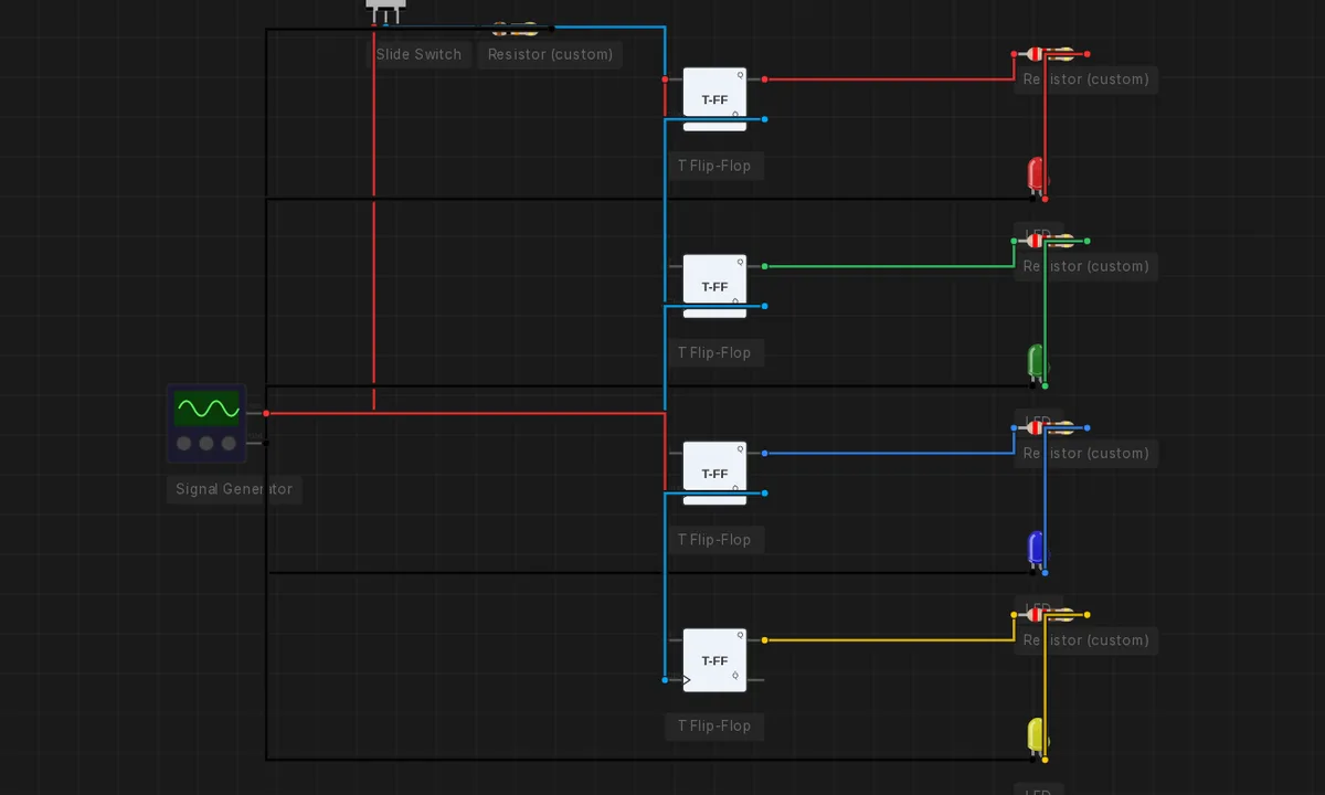
4-Bit Ripple Counter (T flip-flops)
Four T flip-flops chained into a ripple counter — impossible on the SPICE engine (no edge detection at DC). Each time you slide the CLOCK switch from LOW to HIGH the count advances; the four LEDs show it in binary, LSB at the top. The event-driven digital engine evaluates the flip-flops exactly. (Set ?digitalgates=off to see that ngspice cannot run this.)
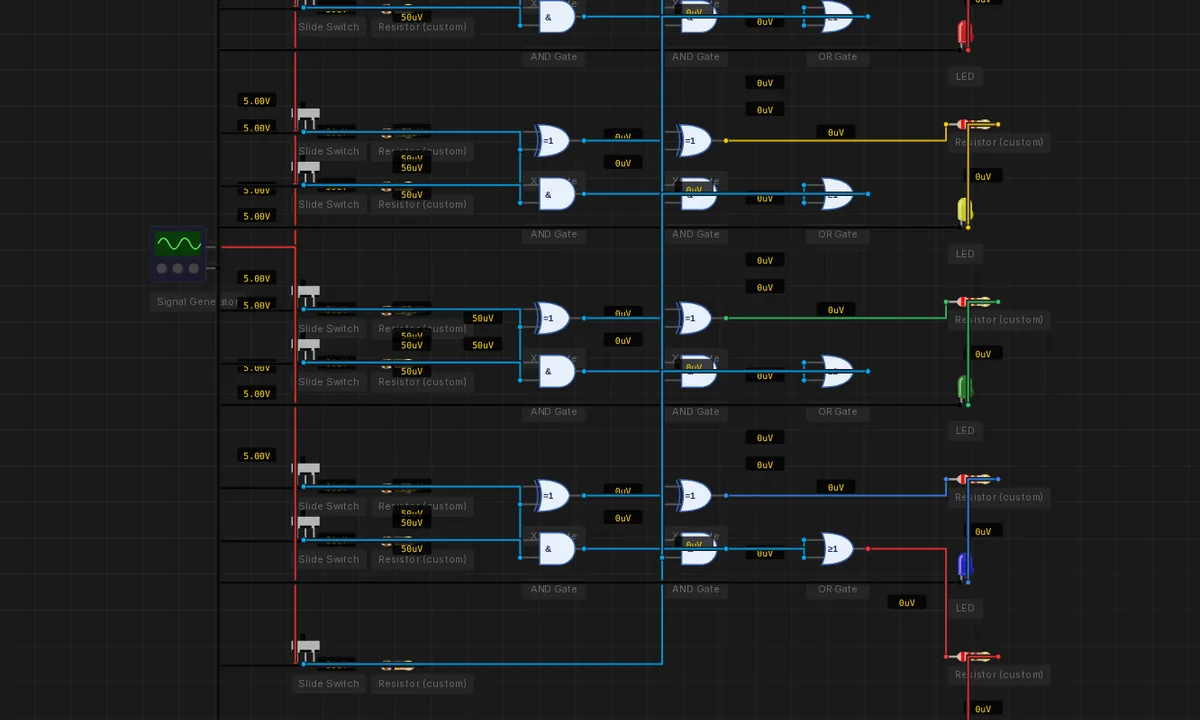
4-Bit Ripple-Carry Adder
Four full adders chained — A[3:0] + B[3:0] + Cin → S[3:0] + Cout. Toggle nine input switches to compute any 4-bit sum live. Twenty-six gates of pure combinational logic.
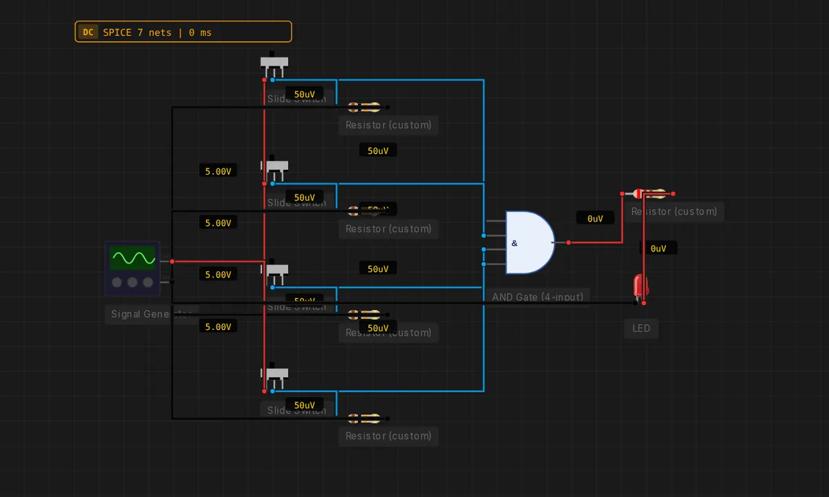
4-Input AND Gate
Four switches feed a single 4-input AND gate. The LED lights only when every input is HIGH at once.
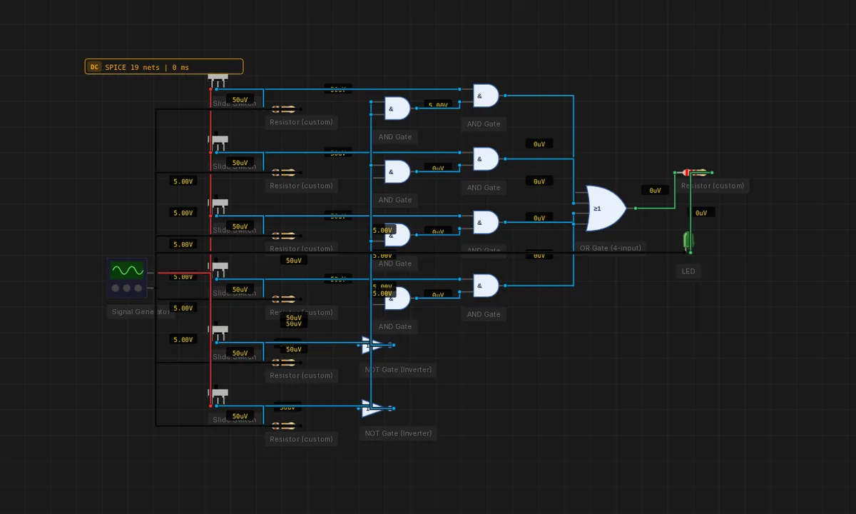
4-to-1 Multiplexer
Two select lines route one of four data inputs to Y. Built from one 2-to-4 line decoder (the !A·!B...A·B combinations) feeding four ANDs into a 4-input OR.
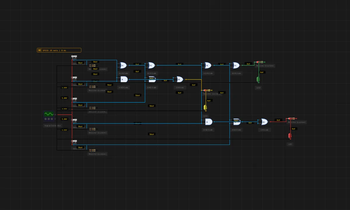
4:2 Compressor (Wallace Cell)
Five same-weight bits in, three out. Two cascaded full adders compress 5 bits into Sum + Carry + Cout in constant time — the building block of Wallace and Dadda tree multipliers.
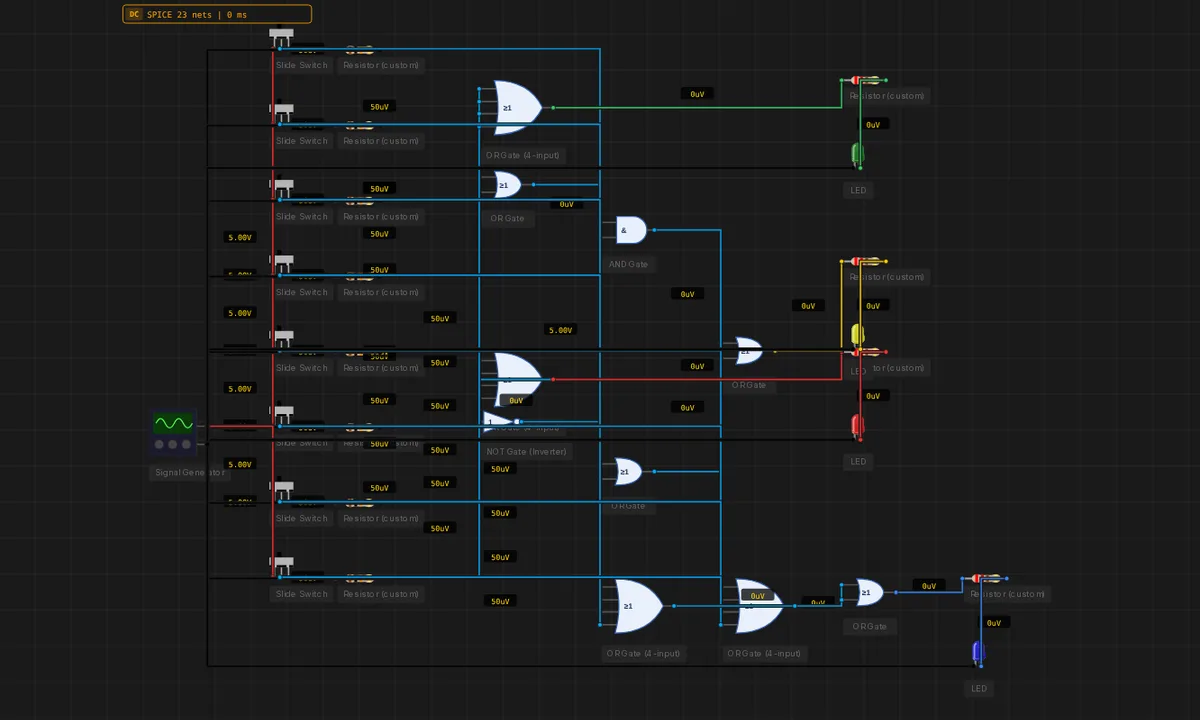
8-to-3 Priority Encoder
Eight input switches; three output LEDs encode the highest-numbered switch that is HIGH as a 3-bit binary number. A fourth "valid" LED lights whenever any input is active.
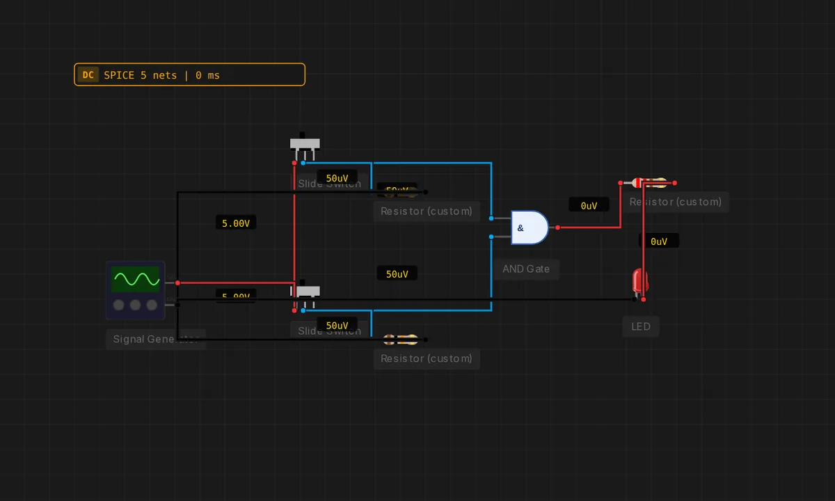
AND Gate — Both Switches
Two slide switches feed an AND gate. The LED lights only when both switches are HIGH.
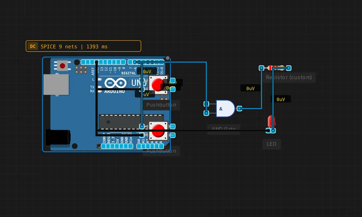
AND Gate Alarm
Two arming switches feed an AND gate — the alarm LED lights ONLY when BOTH are ON (e.g. both doors closed). They are slide switches, so they latch: slide each one ON and it stays, so you can hold both at once. Pure logic, no MCU — runs on the digital gate engine.
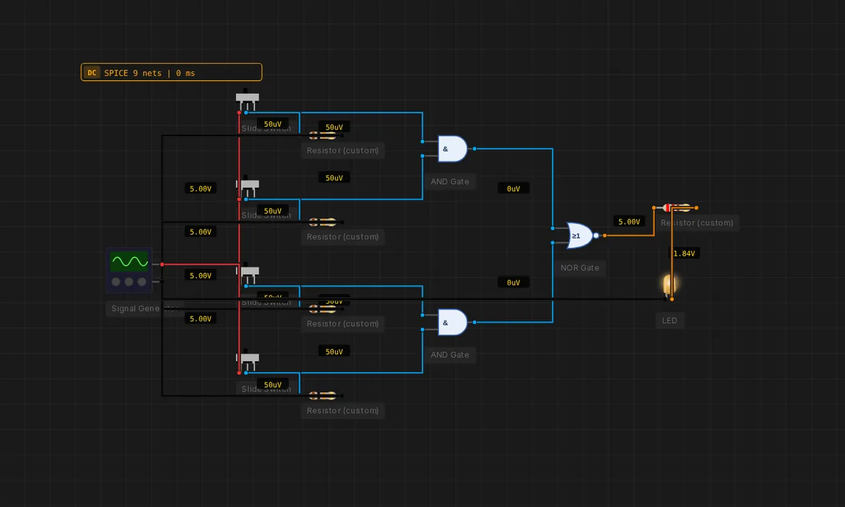
AOI Gate (AND-OR-Invert)
A composite cell common inside CMOS libraries: two ANDs feed a NOR. Output = !((A·B) + (C·D)). Faster than three discrete gates in real silicon.
BCD → 7-Seg: Segment "a"
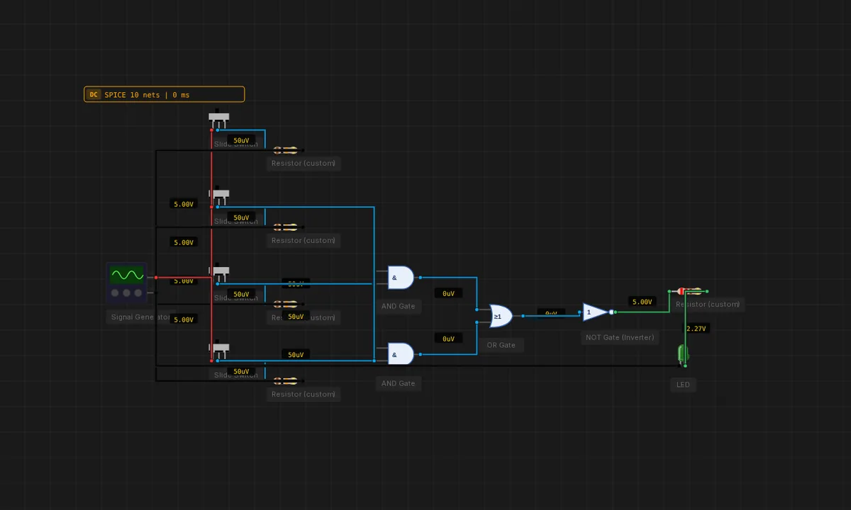
Lights segment "a" for digits 0,2,3,5,6,7,8,9 and leaves it dark for 1 and 4. One slice of a 7447-style decoder, gate-built so the K-map minimisation a = B3 + B1 + B2·B0 + !B2·!B0 is visible end-to-end.
BCD Validity Detector
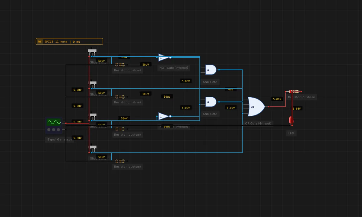
Lights an LED only when the 4-bit input is a valid BCD digit (0–9). The complement (10–15) is detected by B3·B2 + B3·B1 and inverted to drive the "valid" lamp.
Buffer From Three Inverters
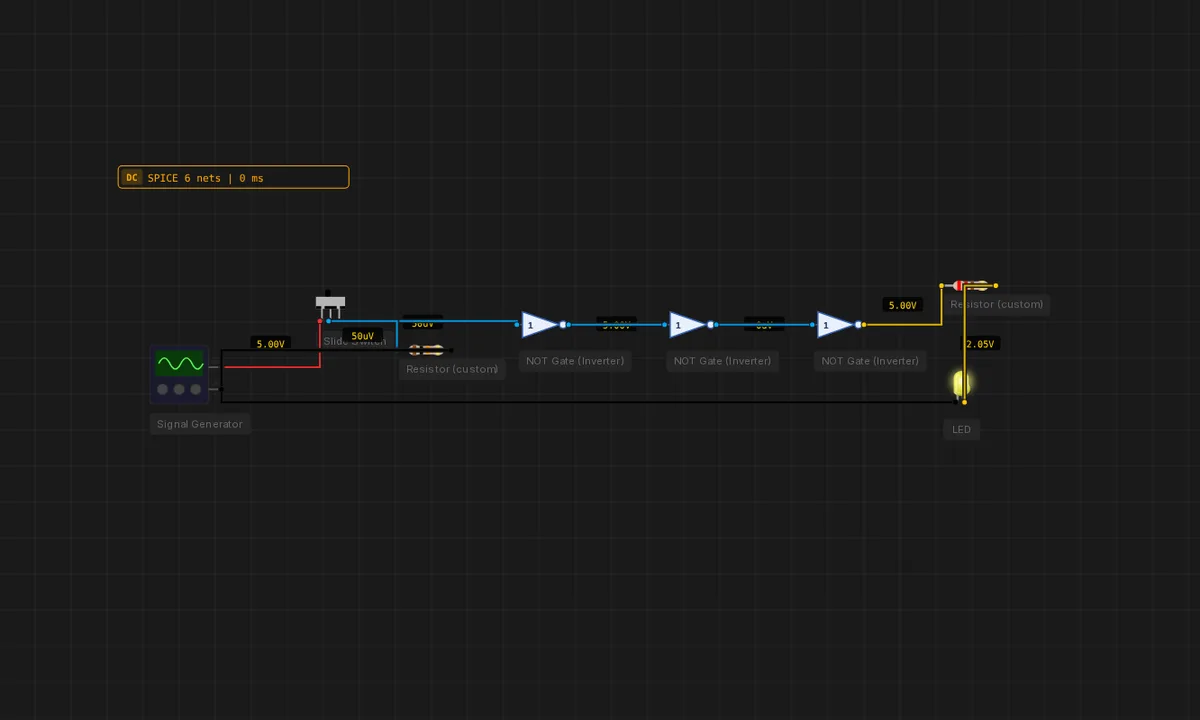
Three NOT gates in series invert three times → effectively a non-inverting buffer with three gate delays. Used for fan-out or to "regenerate" a weak signal.
Full Adder (Gate Level)
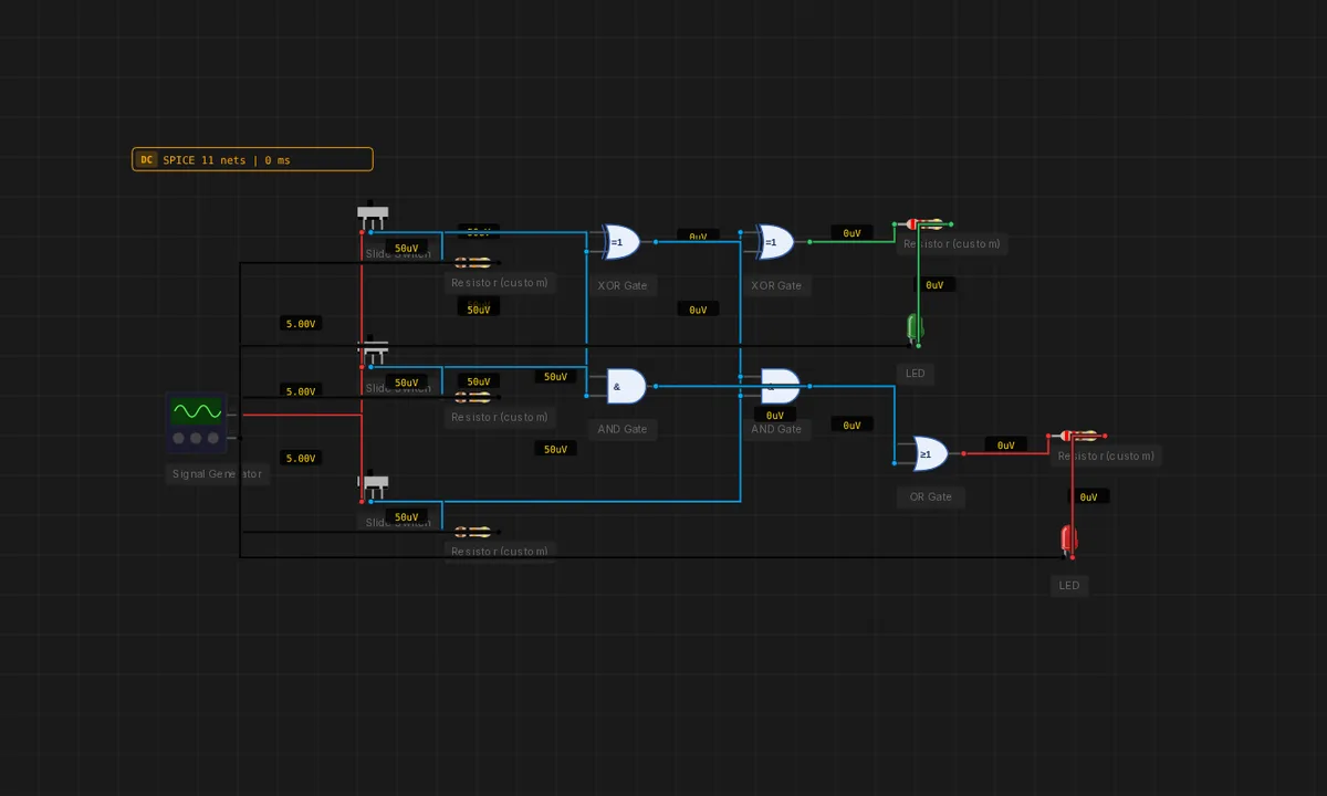
Three inputs — A, B and Cin — feed two XORs, two ANDs and one OR. The XORs give SUM, the OR of the ANDs gives Cout. Classic cascade-able adder cell.
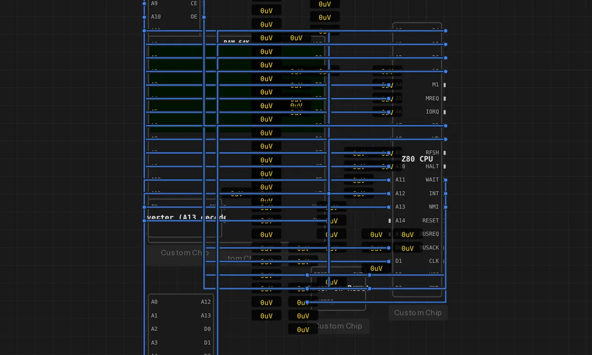
Galaksija — 1983 Z80 home computer
A real 1983 Yugoslav home computer (Voja Antonić, public-domain ROM) built from discrete chips on the bus: a Z80 CPU runs its BASIC ROM, an inverter decodes the address map, a 64K RAM holds memory and renders the text screen from its own video RAM, and a memory-mapped keyboard feeds keystrokes. Click Resume, then click the canvas and TYPE — it boots to "READY" and you can enter Galaksija BASIC, just like the real machine.
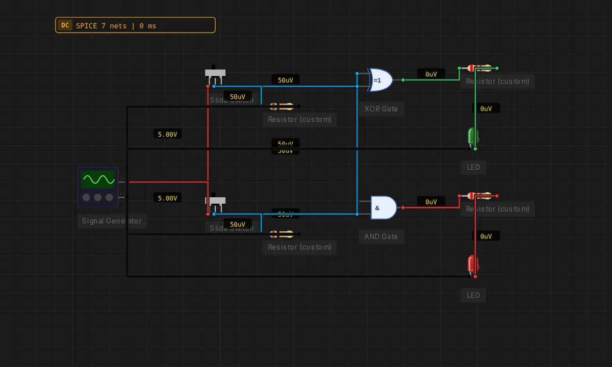
Half Adder
XOR gives the SUM, AND gives the CARRY of two 1-bit numbers A and B. Two LEDs decode the result in real time.
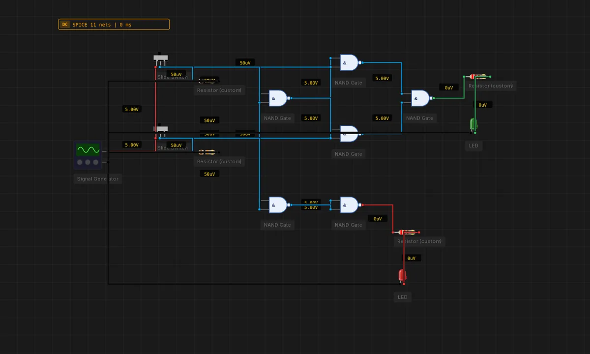
Half Adder — NAND Only
A half adder built entirely from six 2-input NAND gates: four for the XOR sum, two for the AND carry. Proof that NAND alone is functionally complete.
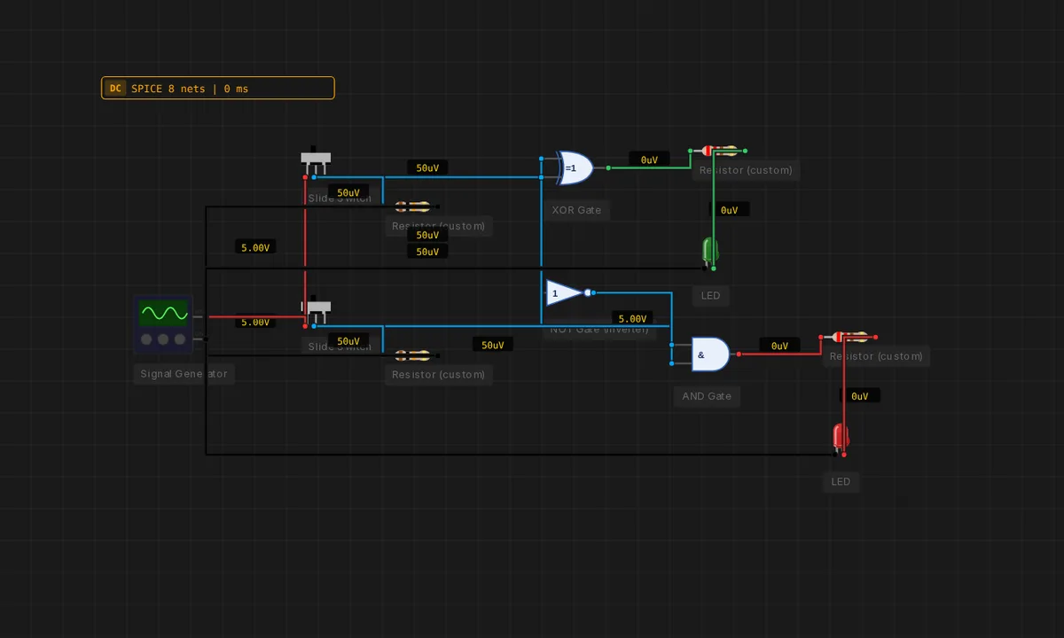
Half Subtractor
Computes A − B for two 1-bit numbers. DIFF = A XOR B, BORROW = !A · B. The complement of the half adder.
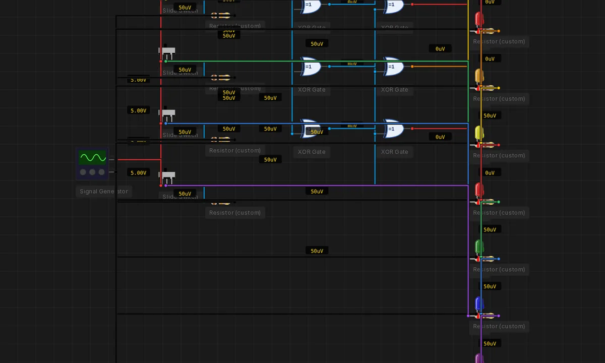
Hamming (7,4) Encoder
Four data bits in, seven coded bits out. Three parity bits computed by XOR triplets implement the classic single-error-correcting code that protects ECC RAM and aerospace memory.
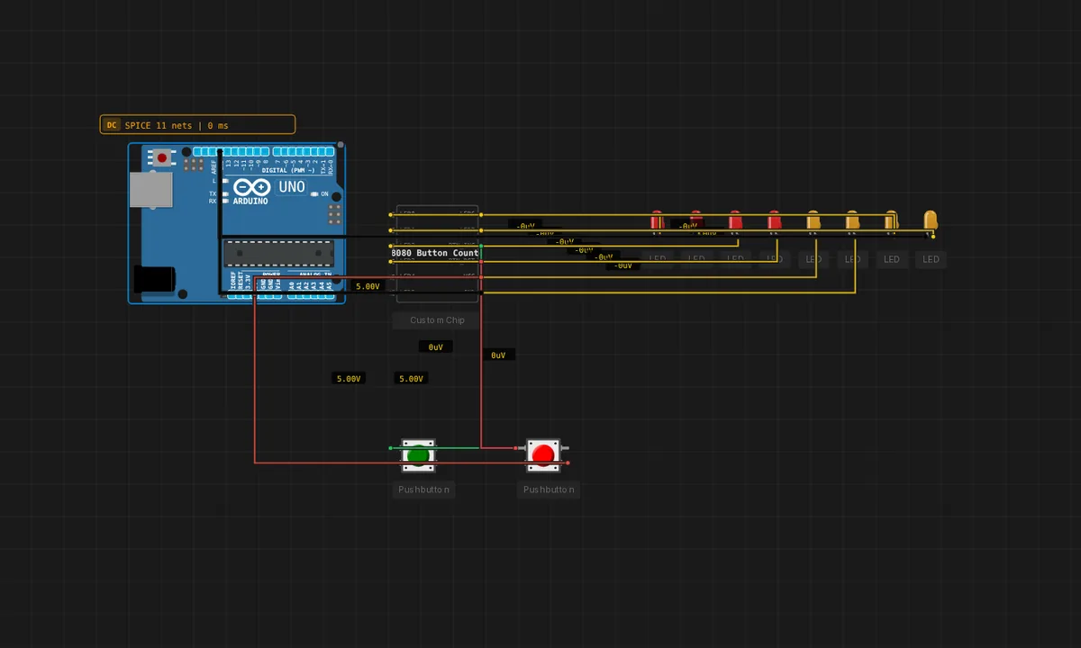
Intel 8080 Button Counter
A self-contained Intel 8080 chip running a 34-byte ROM. Press the INC button to count up in binary on 8 LEDs, press the RST button to clear. The CPU, RAM, and program are all inside the single chip on the canvas.
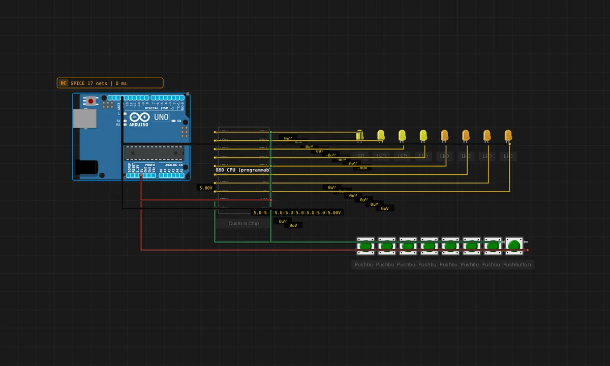
Kill the Bit (1975)
Dean McDaniel's iconic 1975 Altair 8800 reflex game, running on a programmable Intel 8080 chip with NO Arduino — powered by a regulated bench supply. A single LED walks across 8 LEDs; press the matching button at the right moment to kill it. The ROM is killbits.s (the chip's editable program); click Run.
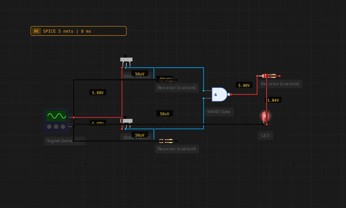
NAND Gate — Universal
NAND is HIGH unless every input is HIGH. The LED stays on except when both switches are HIGH together.
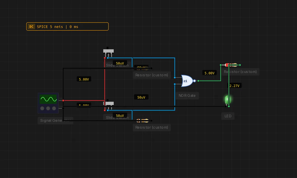
NOR Gate — Idle Lamp
NOR outputs HIGH only when every input is LOW. The LED stays on while both switches sit at LOW.
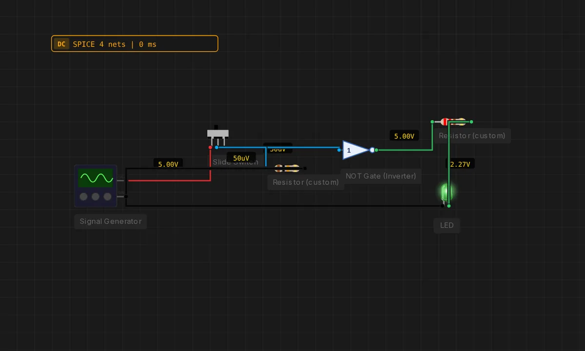
NOT Gate Inverter
A slide switch drives a NOT gate. The LED is normally lit and turns off when the switch is HIGH.
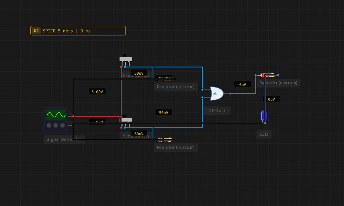
OR Gate — Any Switch
Two slide switches into an OR gate. The LED lights as soon as either switch is HIGH.
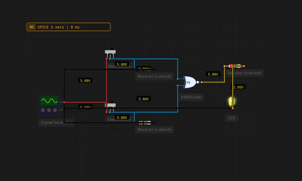
XNOR — Equality Lamp
XNOR outputs HIGH only when both inputs match. A live equality detector — the LED stays lit whenever the two switches share state.
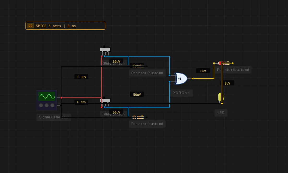
XOR — Difference Detector
XOR fires only when its inputs differ. Flip just one switch — the LED lights. Flip both back to the same — it goes dark.
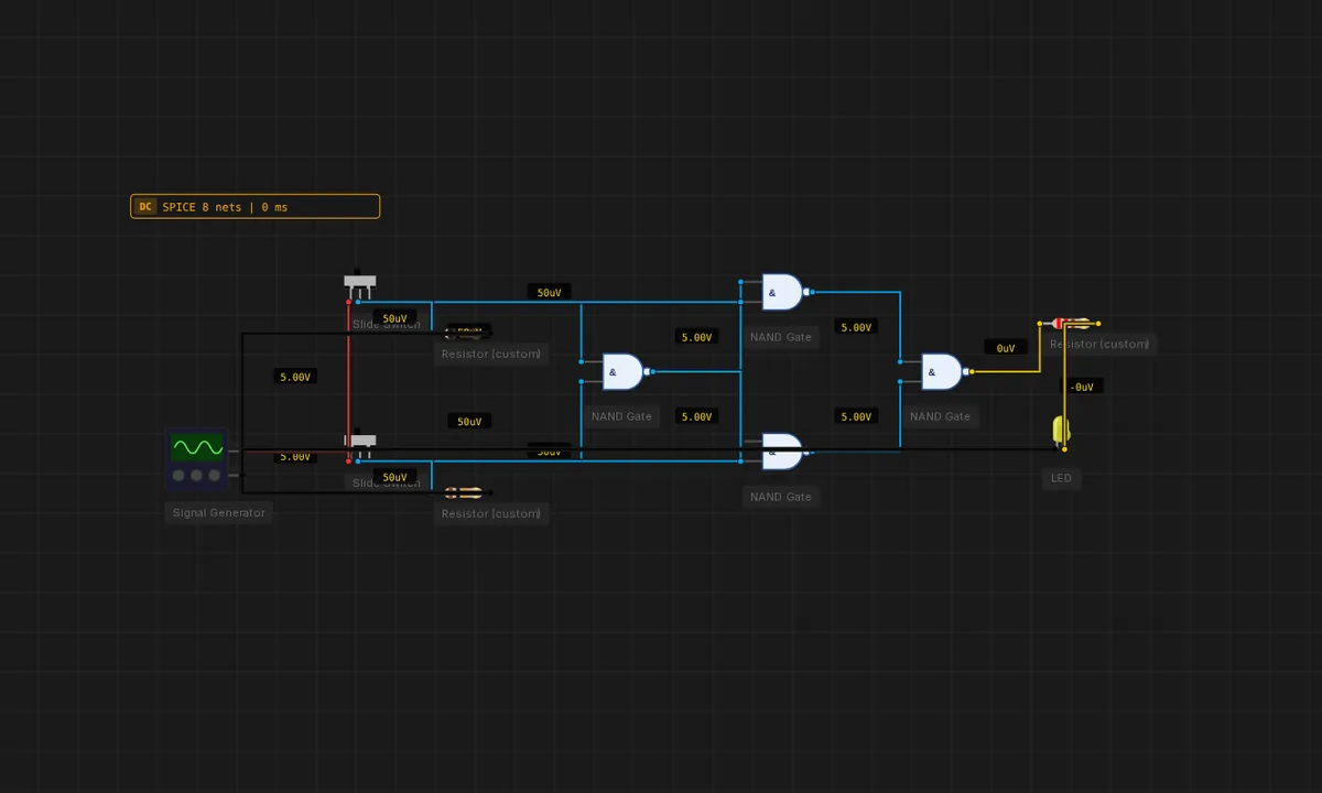
XOR Built From NAND Only
Four 2-input NAND gates form an XOR. Proof that NAND is functionally complete — you can build every gate with just NANDs.
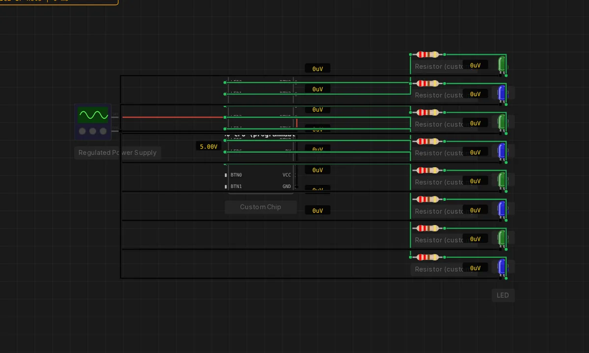
Z80 Comet Scanner
A faster, TWO-LED "comet" sweeps across 8 LEDs on a programmable Z80 chip — a brighter twist on the single-bit Larson. Written in Z80 assembly (scanner.s), NO Arduino: the chip runs standalone on a regulated supply. Click Run.
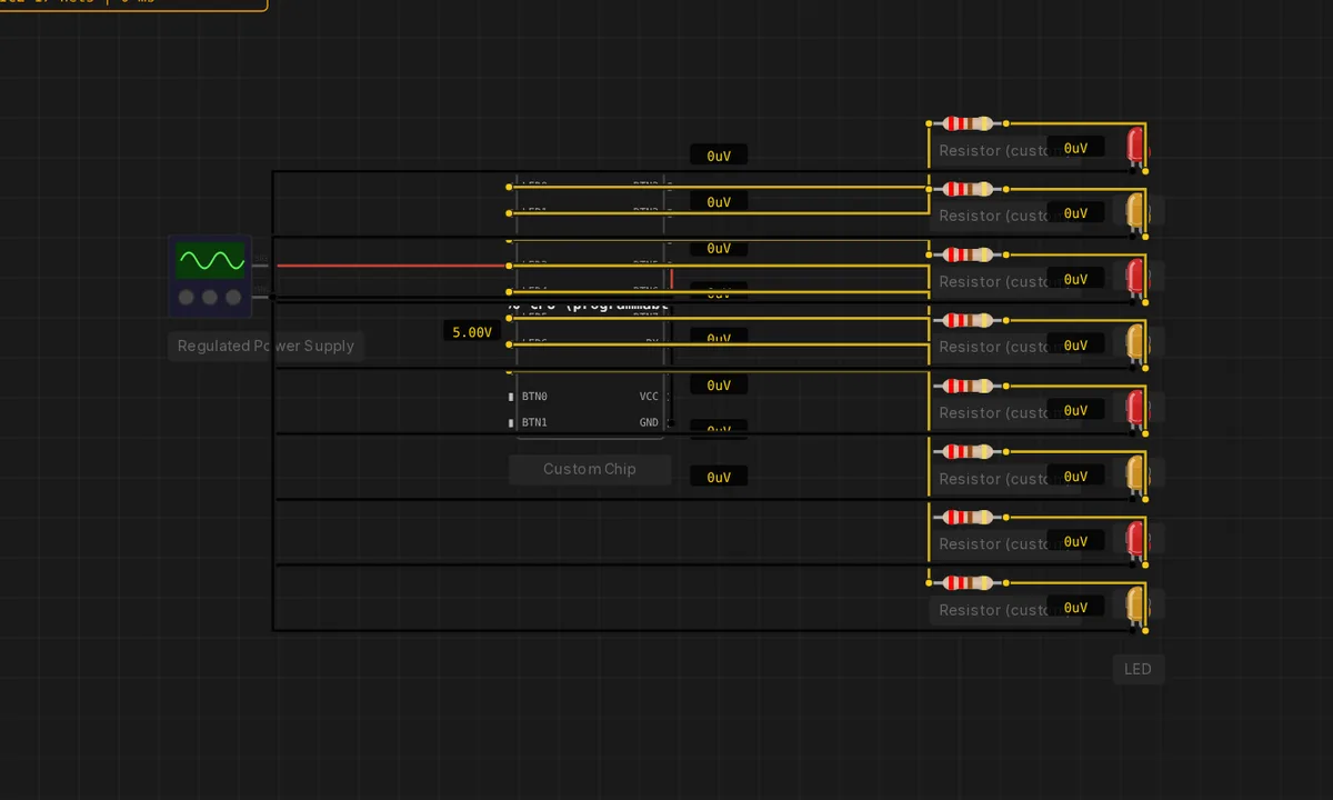
Z80 Larson Scanner (no board)
The programmable Z80 chip drives 8 LEDs with NO Arduino — powered by a regulated bench supply. Velxio runs custom chips as a general-purpose electronics simulator. Click Run: a single LED walks back and forth.
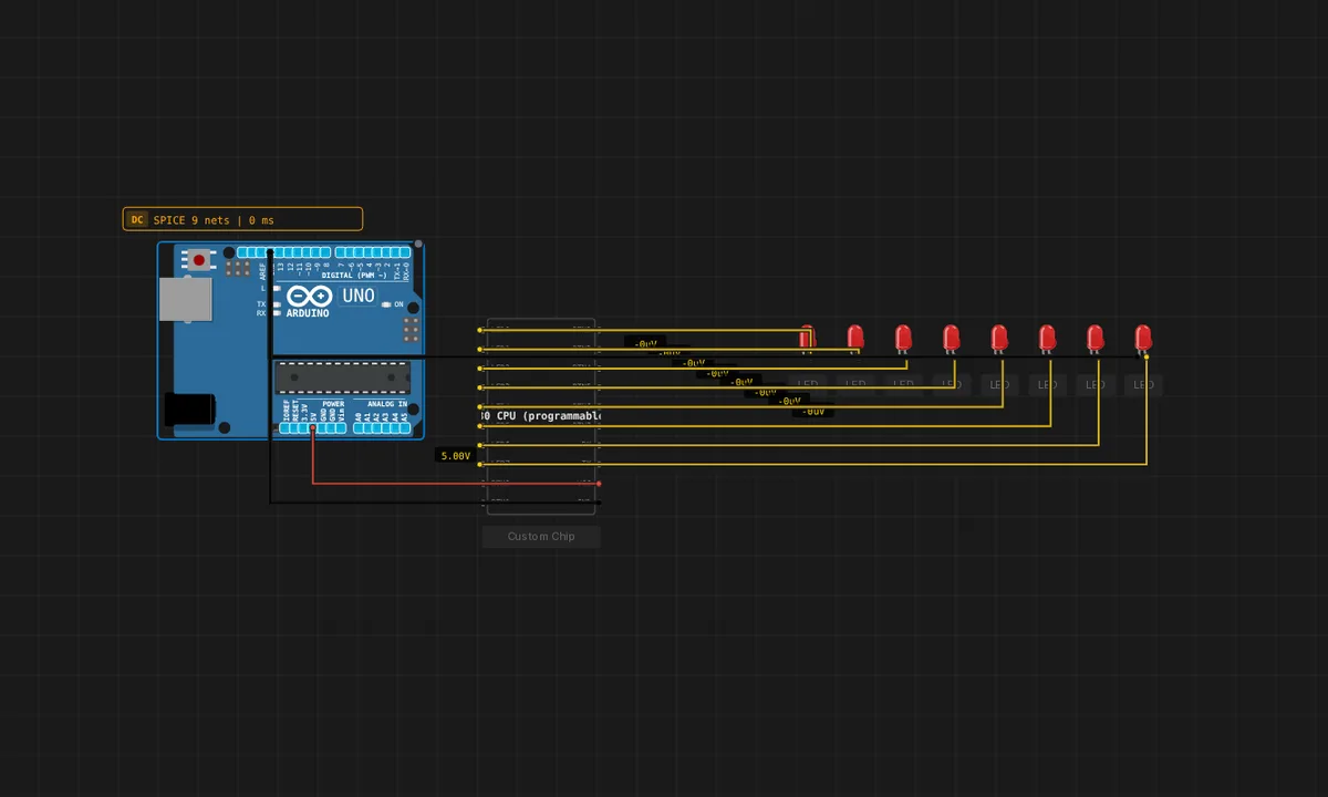
Z80 LED Chaser in C (no board)
A programmable Z80 chip walks a single LED back and forth, Larson-style — but the program is written in C (chaser.c) and compiled to the Z80 by SDCC. No Arduino: the chip runs standalone, powered by a regulated supply. Click Run. Requires sdcc on the backend.
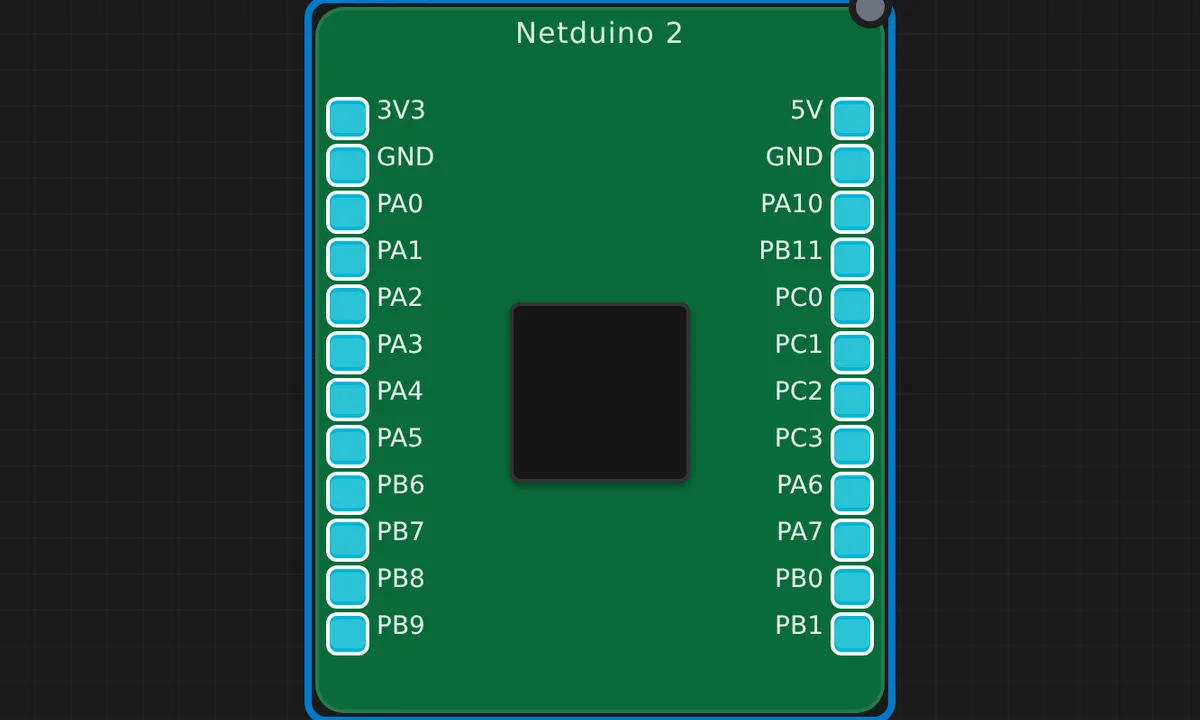
Netduino 2 Serial Counter
Netduino 2 (STM32F205, Cortex-M3) prints an incrementing counter over Serial. GPIO/LED support arrives once the F205 SoC is wired; serial works today under QEMU.
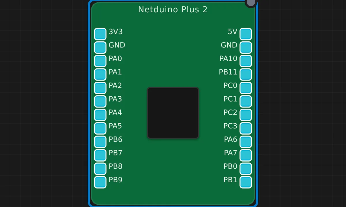
Netduino Plus 2 Blink
Blink the onboard PA10 LED and print to Serial on a Netduino Plus 2 (STM32F405, Cortex-M4) under QEMU.
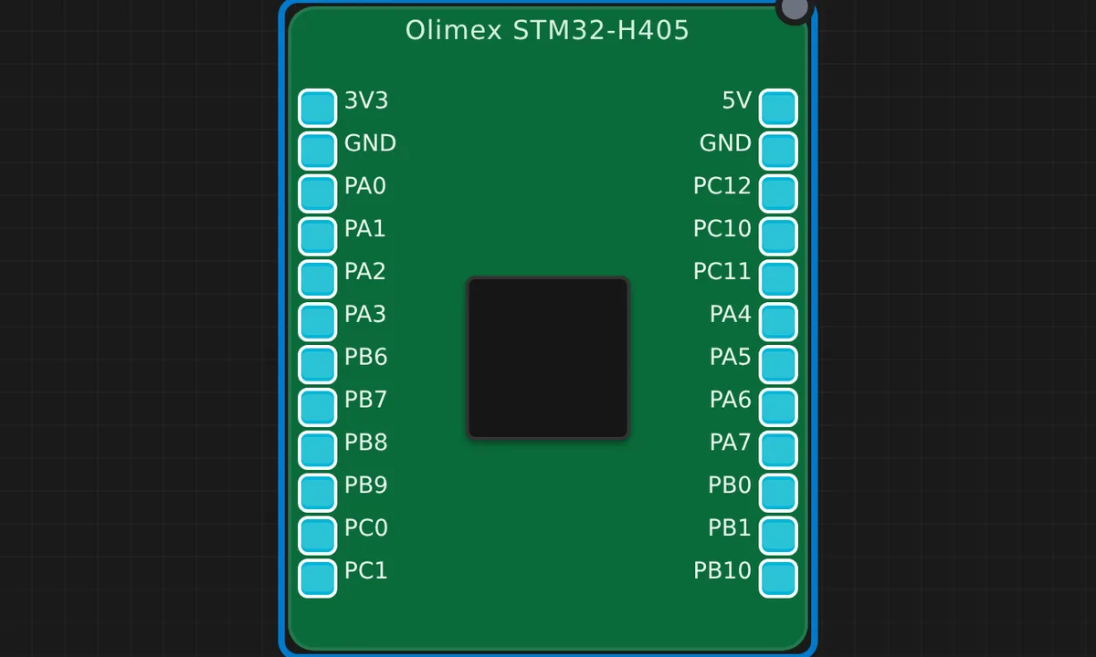
Olimex STM32-H405 Blink
Blink the onboard PC12 status LED and print to Serial on an Olimex STM32-H405 (STM32F405RG, Cortex-M4) under QEMU.
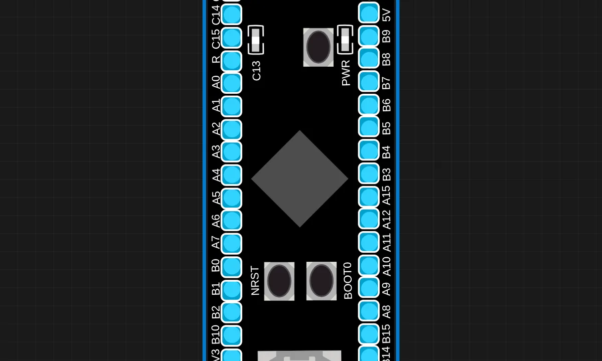
STM32 Black Pill (F401) Blink
Blink the onboard PC13 LED and print to Serial on an STM32F401CE Black Pill (Cortex-M4) under QEMU.
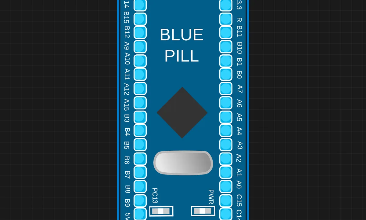
STM32 Blue Pill (F103CB) Blink
Blink the onboard PC13 LED and print to Serial on an STM32F103CB Blue Pill (Cortex-M3, 128KB flash) under QEMU.
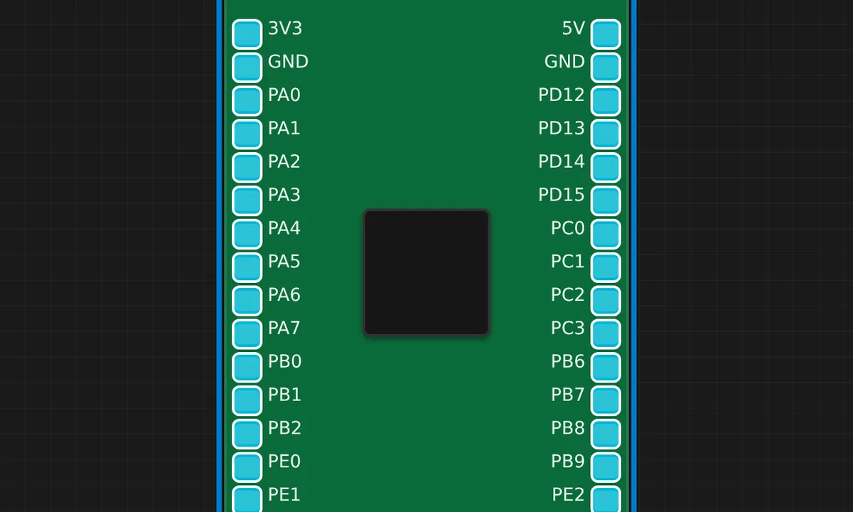
STM32F4 Discovery LED Blink
Blink the onboard PD12 green LED and print to Serial on an STM32F4 Discovery (STM32F407VG, Cortex-M4) under QEMU.